|
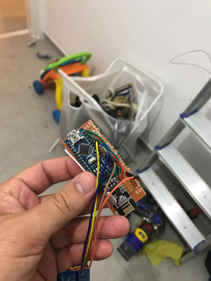
when I was building my custom light 4 touch switch panel for my smartHomeDIY I discovered Arduino uno and nano has only 2 hardware interrupts, luckly,after searching for a while, I found a blog that helped me to overcome this limitation. The solution is: pin change interrupts which are supported by the Arduino uno and nano: . Regular hardware interrupts can be registered for raising or falling or change interrupt, but the pin change interrupts, as their name suggests, are only capable to deliver interrupts when the pin senses a voltage change in any direction, if you need to know which pin was changed you will have to read all pin states (or relevant pins) to know the new state and compare it to the old state (which you have to save on you program. a small workaround in my case was to register for 2 hardware interrupts and for the other 2 required interrupts I used the pin chagne mechanism, but there are good news, the pin change interrupts are grouped into group of pins
 To read more about this topic I recommend the following:
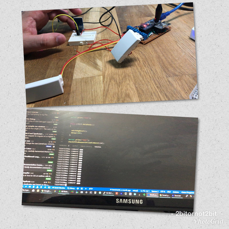
When writing code and delivering to customers you usually will find your self (or someone else ...) debugging your code throw log files and probably a lot of them. I know I do :)  So I wrote my self a small helper tool based on Electron and vue.js + vuetifyjs. which makes it cross-platform.
And I made is open source just for you :) Logx You can just drag and drop you files on it and start 'finding' , setting colors for specific phrases or filtering in or out any phrase you like. Enjoy. BTW I used this cool template code from github, to get started easily... Just note that this is a work-in-progress, feel free to file in issue you find on github :)  If you like your realtime logs monitoring on terminal from anywhere while using your favourite searching and colouring tools like me, then you must read this.
Azure DC/OS is a great tool, but getting the logs from each microservice instance using the dashboard is slow and complected. So for the rescue here comes dc/os CLI. This command line utility will make you life much easier in just a couple of steps
Good luck and happy debugging ... :)
During my search to start and learn embedded system programming, I was not able to find a good reference to start with.
I was searching a reference that will easy me in into this topic. Because this topic not only hard to learn it is also consists from several topics:
So after searching a lot and for a long time I came up with the following YouTube playlists and couple of links that will ease you into this very interesting field. Embedded Step 1
Embedded Step 2
communicationsRandom important topicsSimple Electronics Basics
Tools
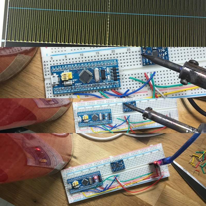
Today I wanted to talk about a video that inspired me by Joop Brokking
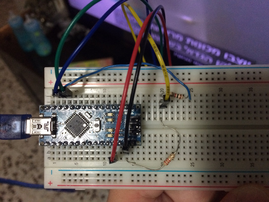
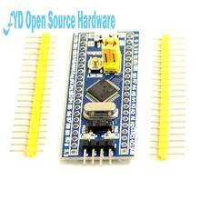
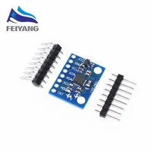
it’s a tutorial video about STM32F103C8T6 ARM STM32 Minimum System Development board known also as the Blue Pill and how to program it to use the MPU-6050 sensors board via I2C
In this video Joop tested the i2c communication from the MPU-6050 sensors board to the STM32F103C8T6 ARM-M3 Micro controller
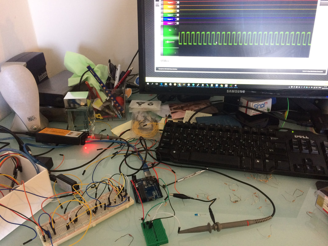
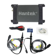
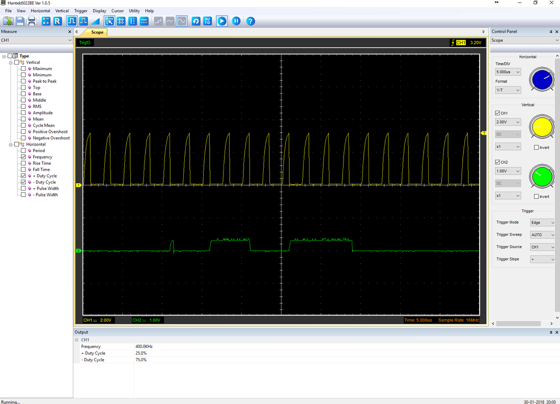
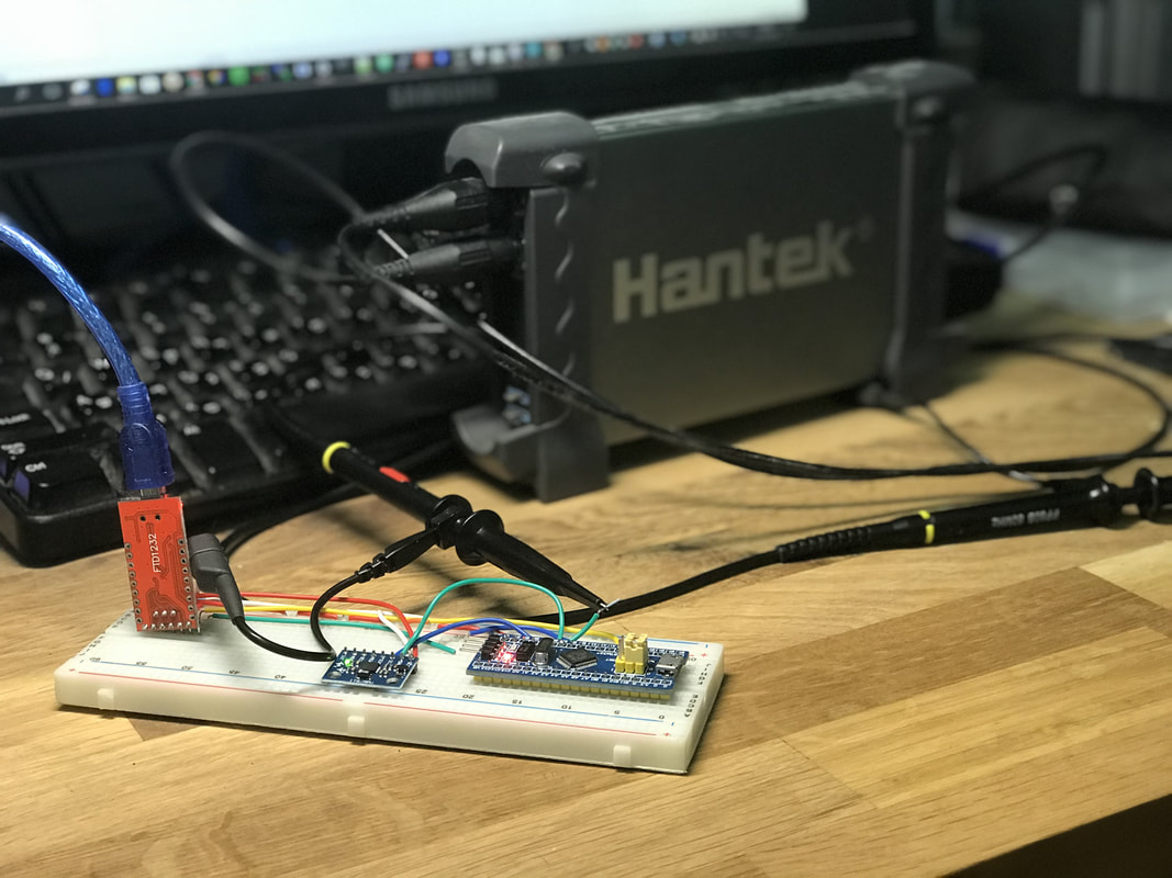
He used a real hardware Oscilloscope to test the signal and show the errors and how to fix them These hardware Oscilloscopes are very useful but could also be quite expensive, especially for a beginner So I thought why not replicate the hardware setup and try the same experiment with my Hantek 6022BE PC USB Digital portable Oscilloscope And see how the single looks like or if it’s even capable measuring these kind of signals
The Hantek 6022BE PC USB Digital portable Oscilloscope, is a PC USB Digital portable Oscilloscope that features 2 20MHz analog Channels at 48M, and single can be shown on the computer with a dedicated software that comes with it
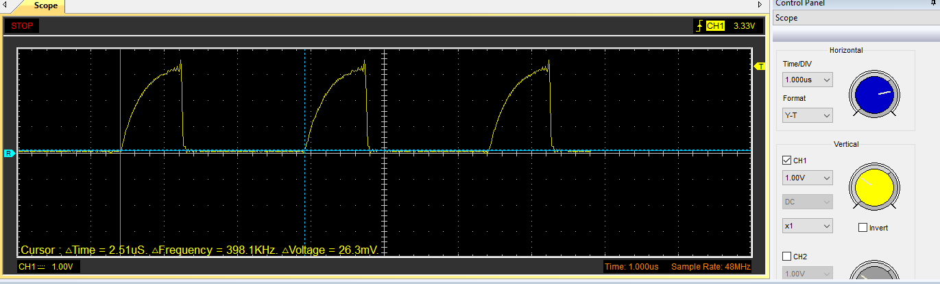
I have tested the 100KHz and 400KHz with no problem You can see the clock signal and the data signal As can be seen here it works great and it only costs around 70$
There are multiple ways to investigate the signal
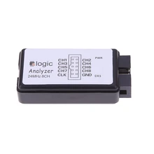
and the software has some nice measuring capabilities But of course it has less features than the hardware ones and probably will not work at the higher scales of Mhz signals I have also tried the same experiment with my USB 24MHz 8 Channel Logic Analyzer and the results were also great and this one only costs around 10$, but cannot debug analog signals only digital ones (i2c, spi, UART , etc...) 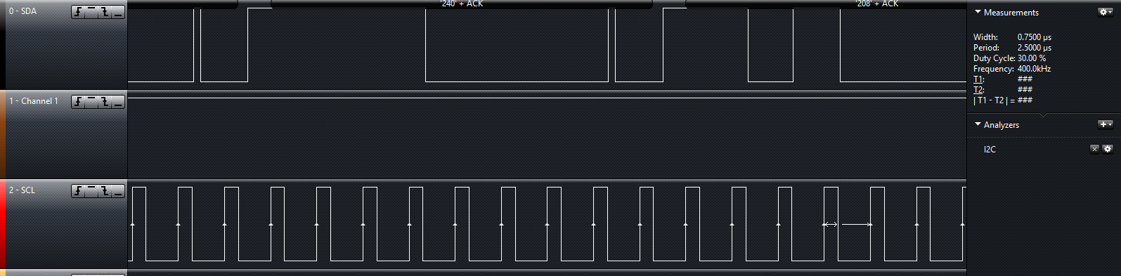
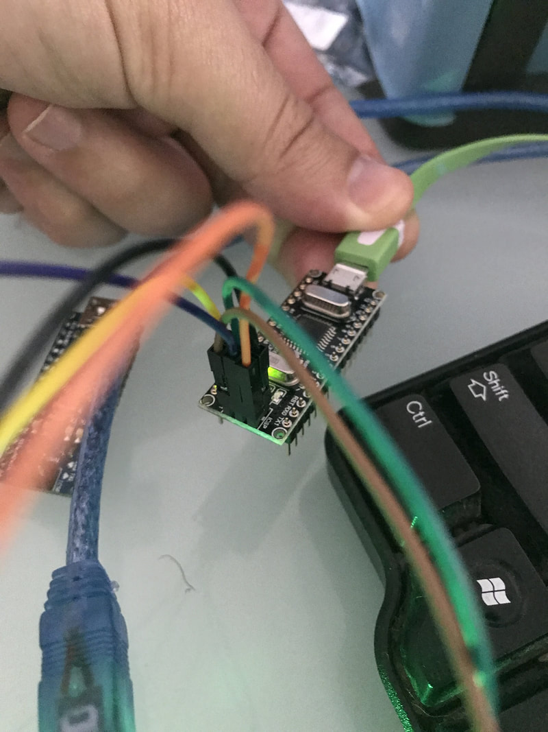
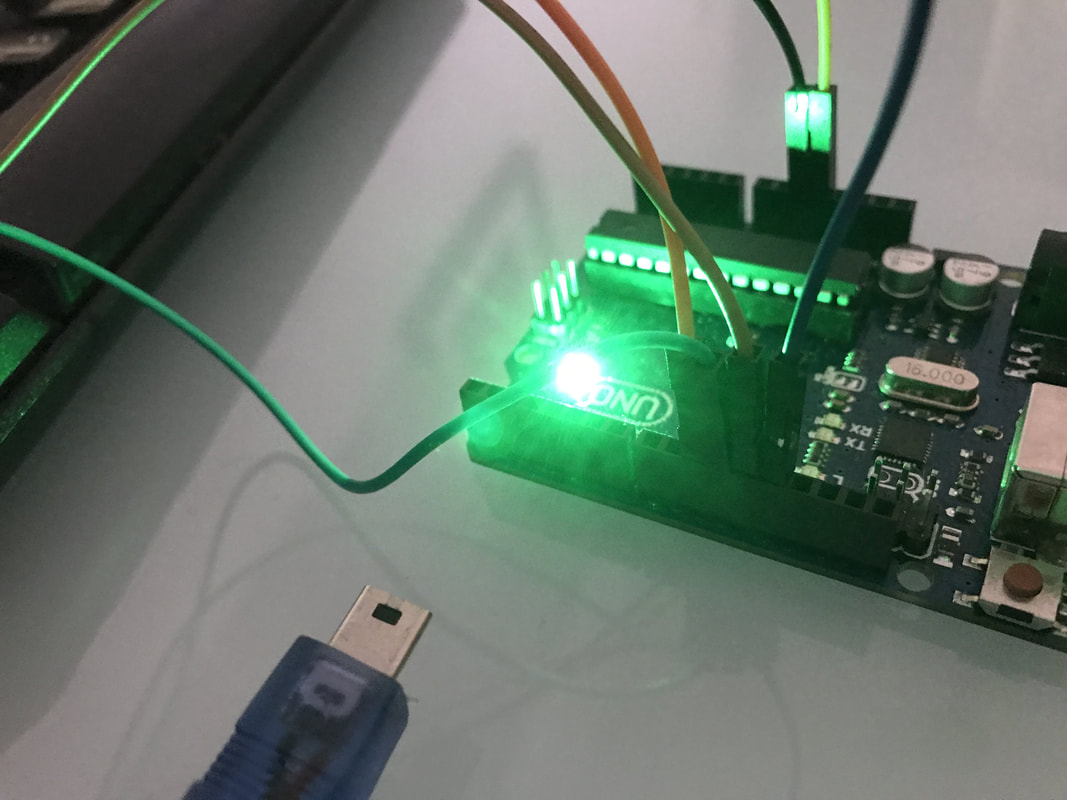
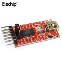
To program the STM32 you will beed an FTDI programer connected to the STM32 B6 and B7
Check out the full tutorial about programming the STM32F103C8T6 here
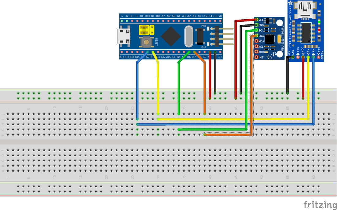
I2C test
|


 RSS Feed
|
|
|