|
Today I wanted to talk about a video that inspired me by Joop Brokking
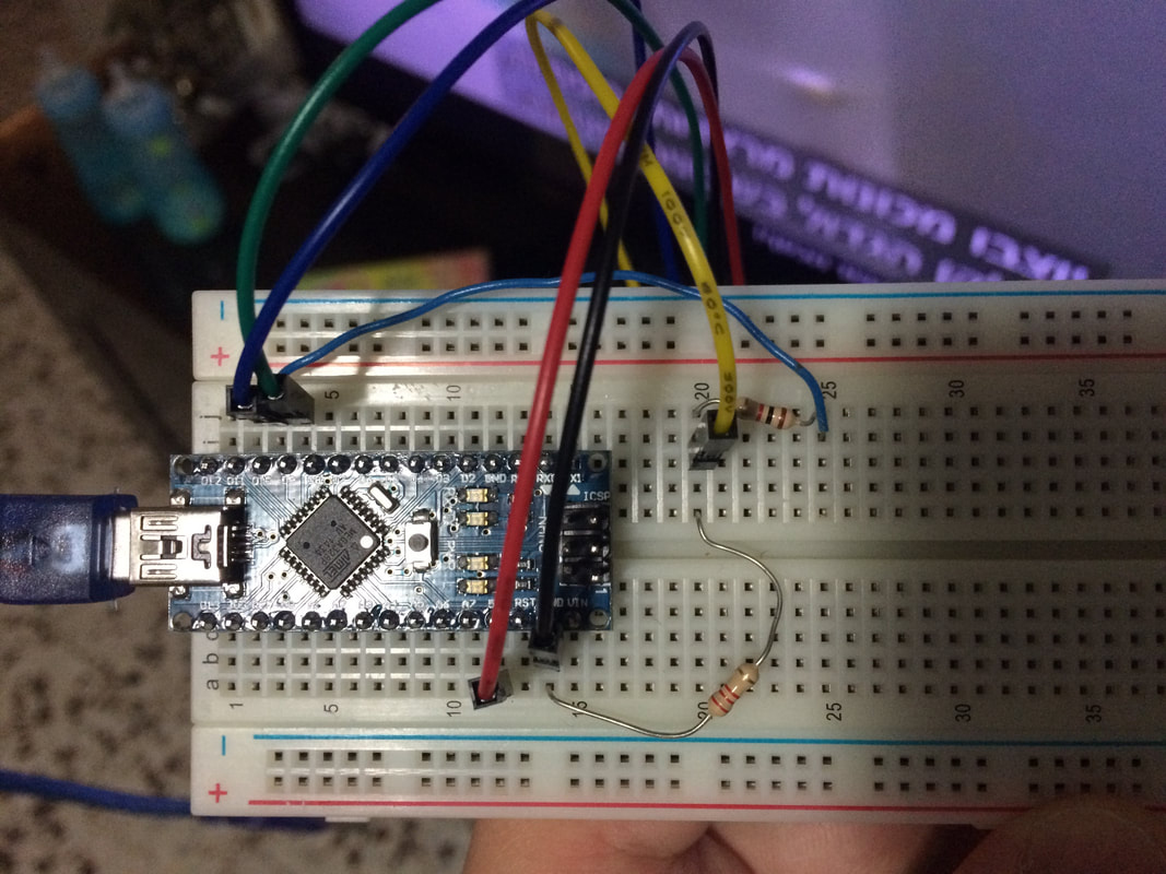
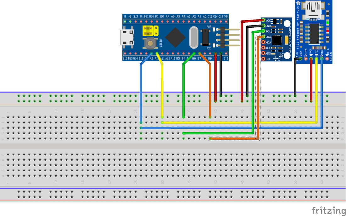
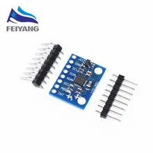
it’s a tutorial video about STM32F103C8T6 ARM STM32 Minimum System Development board known also as the Blue Pill and how to program it to use the MPU-6050 sensors board via I2C
In this video Joop tested the i2c communication from the MPU-6050 sensors board to the STM32F103C8T6 ARM-M3 Micro controller
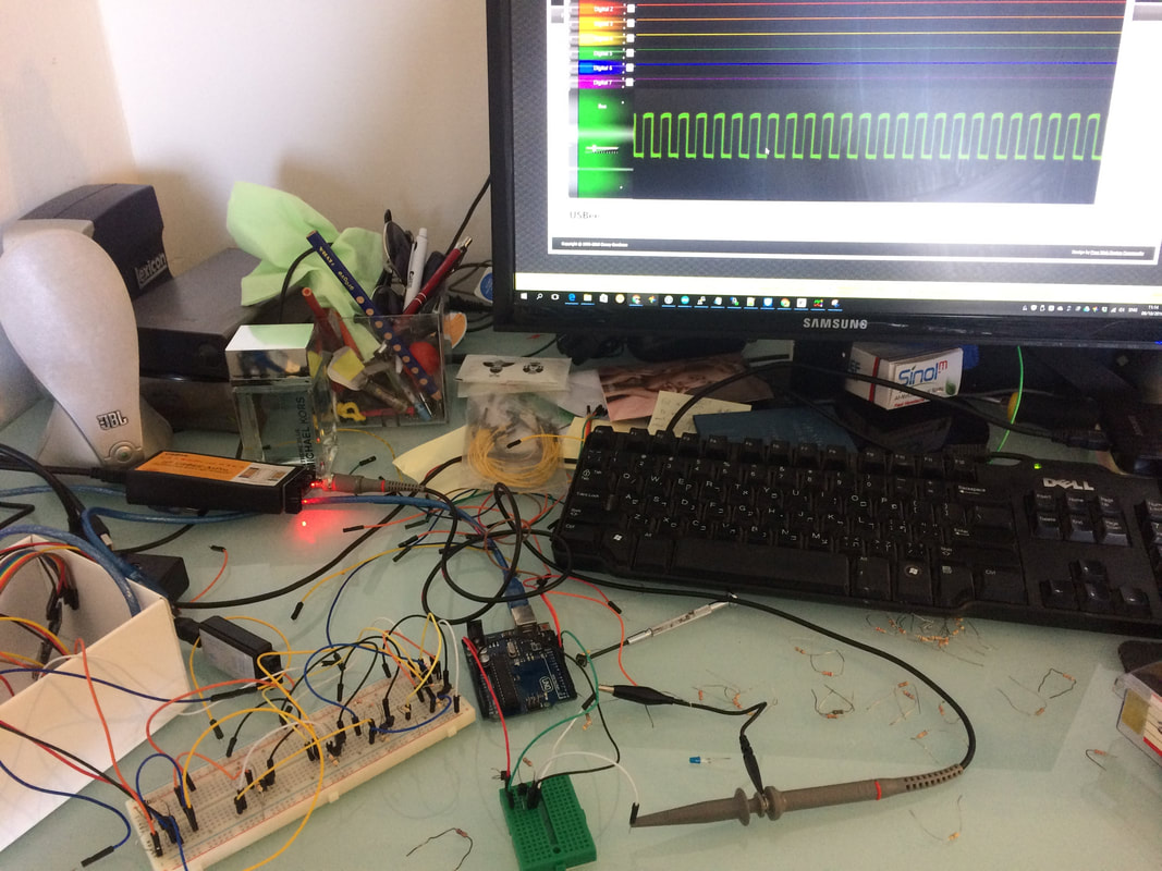
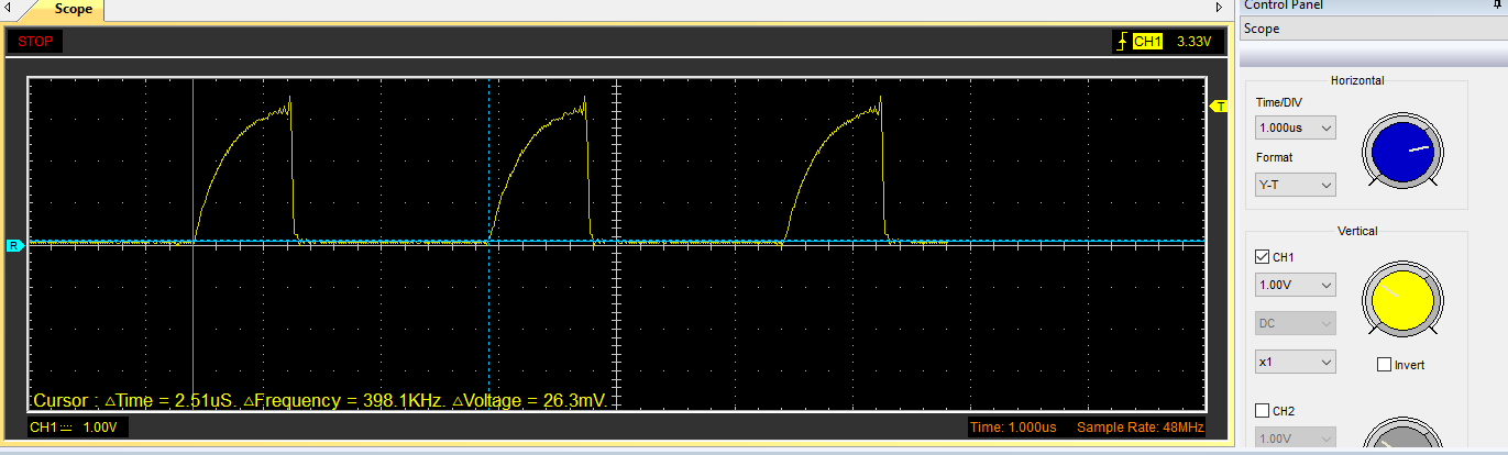
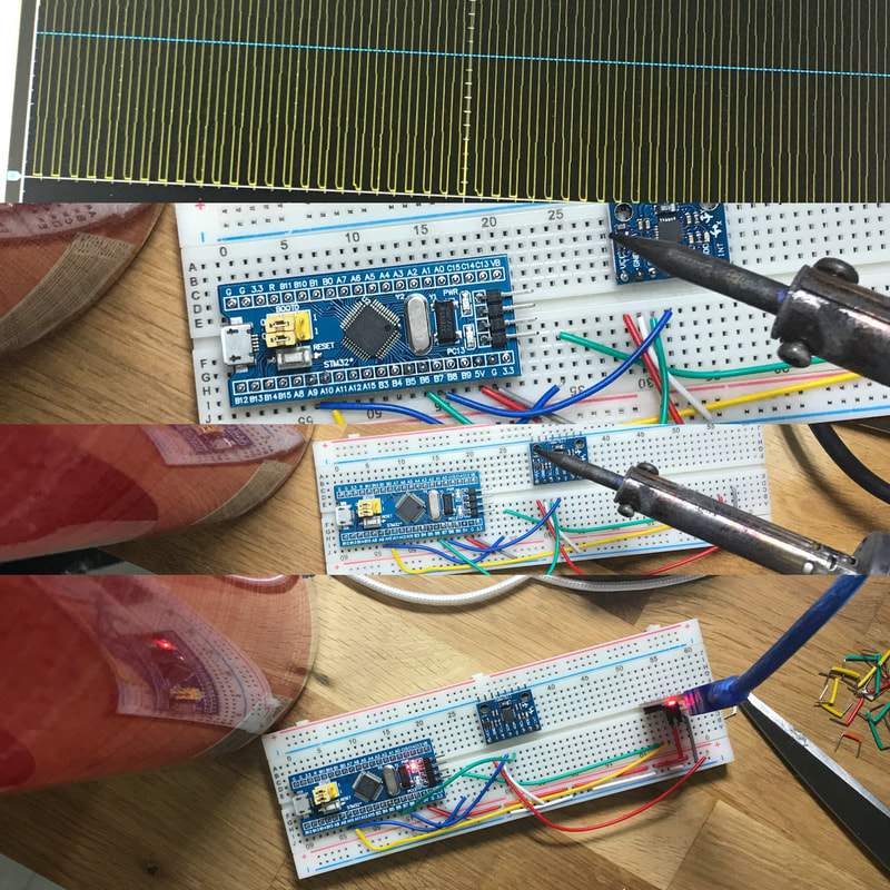
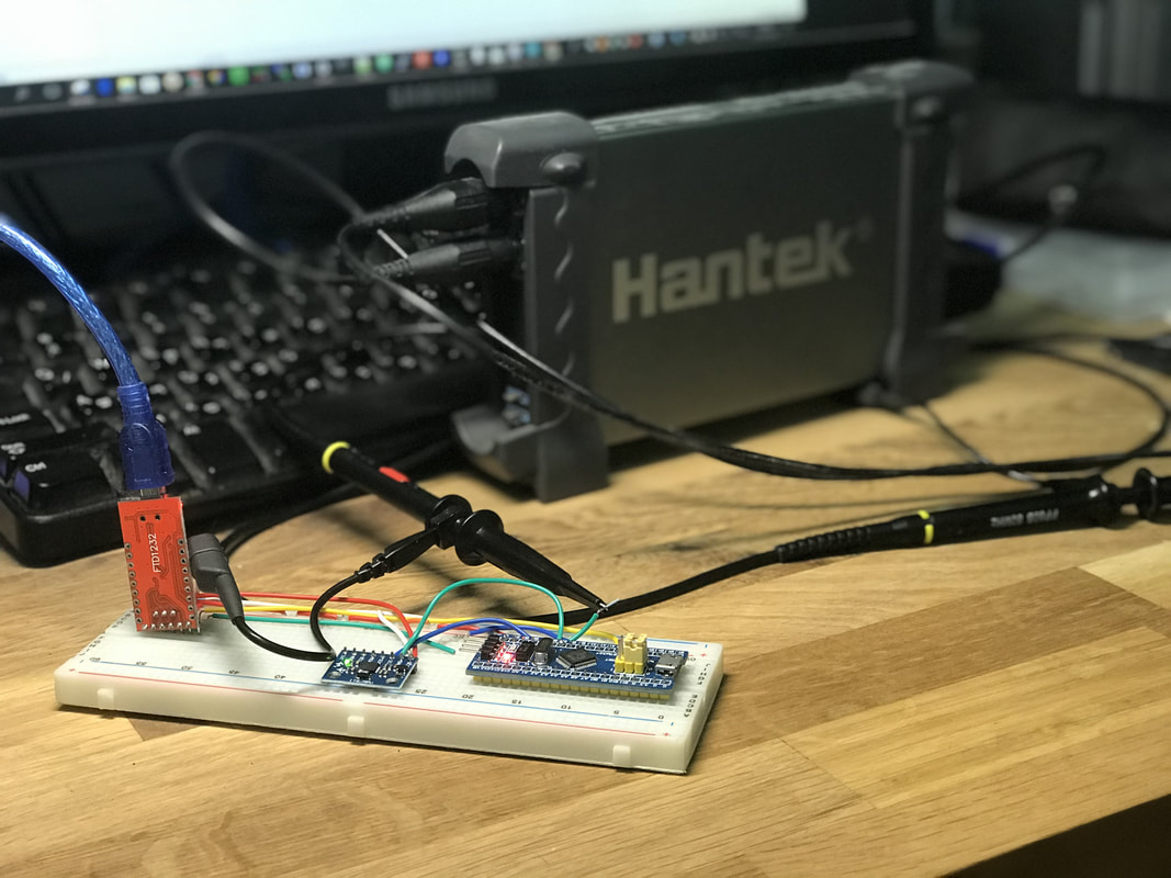
He used a real hardware Oscilloscope to test the signal and show the errors and how to fix them These hardware Oscilloscopes are very useful but could also be quite expensive, especially for a beginner So I thought why not replicate the hardware setup and try the same experiment with my Hantek 6022BE PC USB Digital portable Oscilloscope And see how the single looks like or if it’s even capable measuring these kind of signals
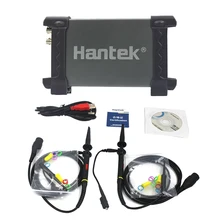
The Hantek 6022BE PC USB Digital portable Oscilloscope, is a PC USB Digital portable Oscilloscope that features 2 20MHz analog Channels at 48M, and single can be shown on the computer with a dedicated software that comes with it
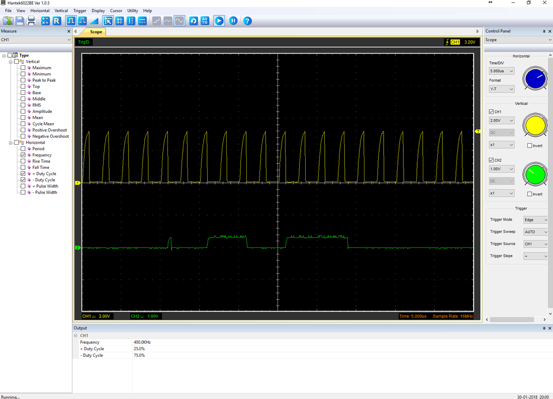
I have tested the 100KHz and 400KHz with no problem You can see the clock signal and the data signal As can be seen here it works great and it only costs around 70$
There are multiple ways to investigate the signal
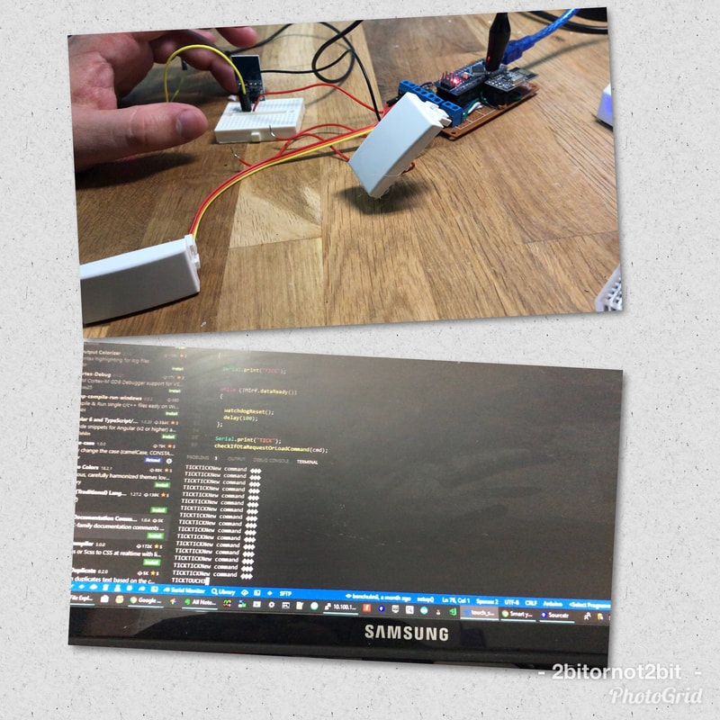
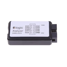
and the software has some nice measuring capabilities But of course it has less features than the hardware ones and probably will not work at the higher scales of Mhz signals I have also tried the same experiment with my USB 24MHz 8 Channel Logic Analyzer and the results were also great and this one only costs around 10$, but cannot debug analog signals only digital ones (i2c, spi, UART , etc...) 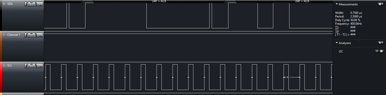
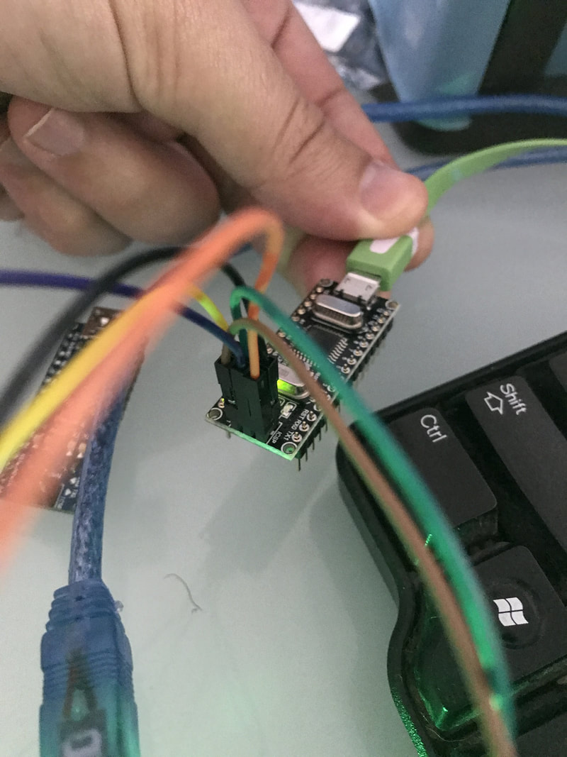
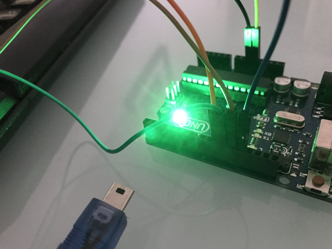
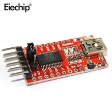
To program the STM32 you will beed an FTDI programer connected to the STM32 B6 and B7
Check out the full tutorial about programming the STM32F103C8T6 here
I2C test
Meet
11/16/2019 05:43:14 am
How to show output from sensor
F.K.
4/1/2020 12:39:54 pm
Thank you!! Comments are closed.
|


 RSS Feed
|
|
|