|
During my search to start and learn embedded system programming, I was not able to find a good reference to start with.
I was searching a reference that will easy me in into this topic. Because this topic not only hard to learn it is also consists from several topics:
So after searching a lot and for a long time I came up with the following YouTube playlists and couple of links that will ease you into this very interesting field. Embedded Step 1
Embedded Step 2
communicationsRandom important topicsSimple Electronics Basics
Tools
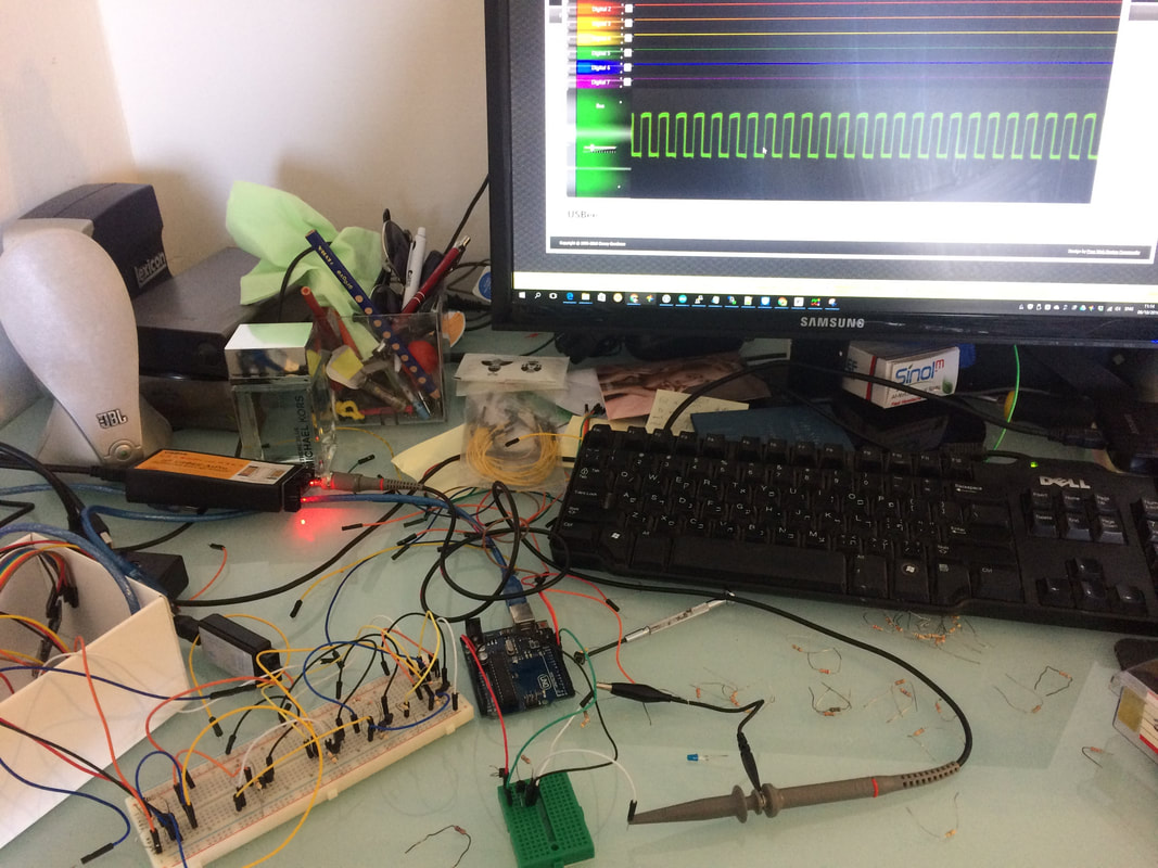
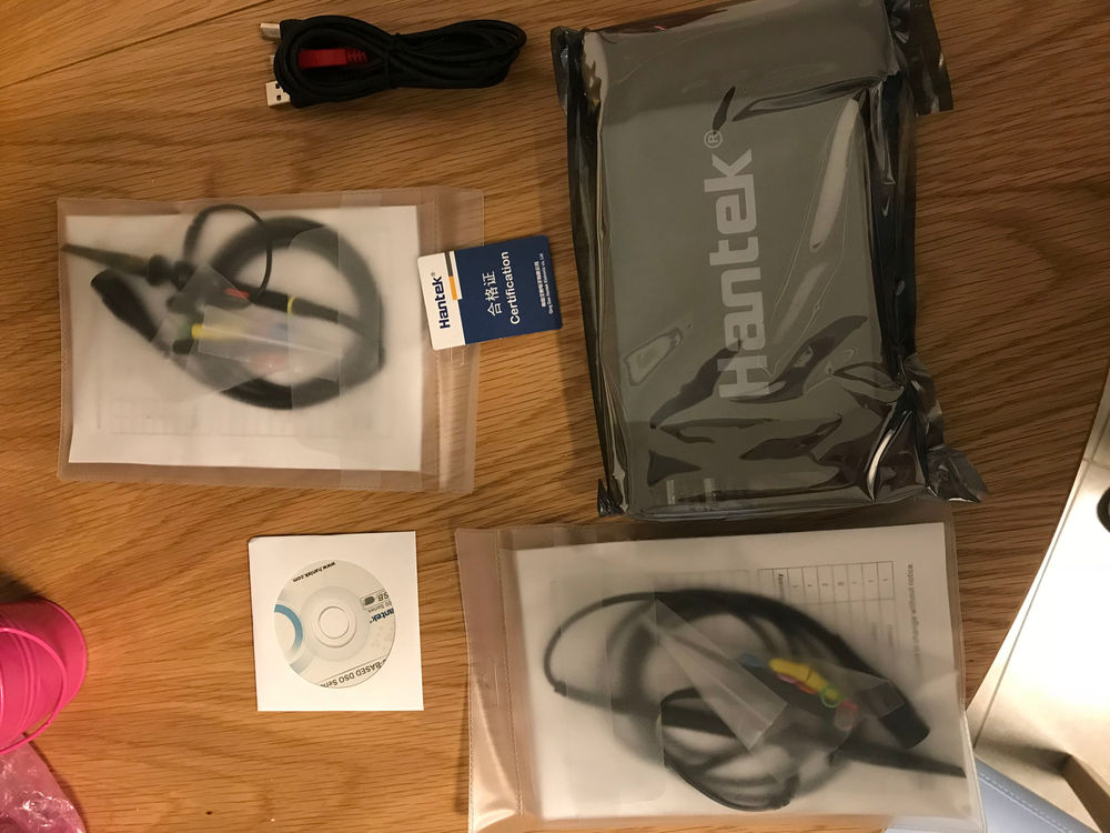
To trail and error with Arduino sketchs you will need some tools, one of them is an oscilloscope, lets learn the basics of this important tool.
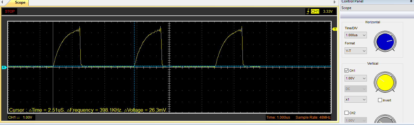
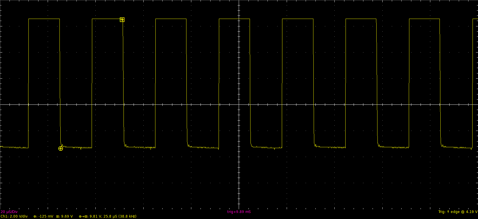
An oscilloscope is a debugging tool for electronics circuits where you can prob any point and check out the signal in watch it in real time (voltage over time)
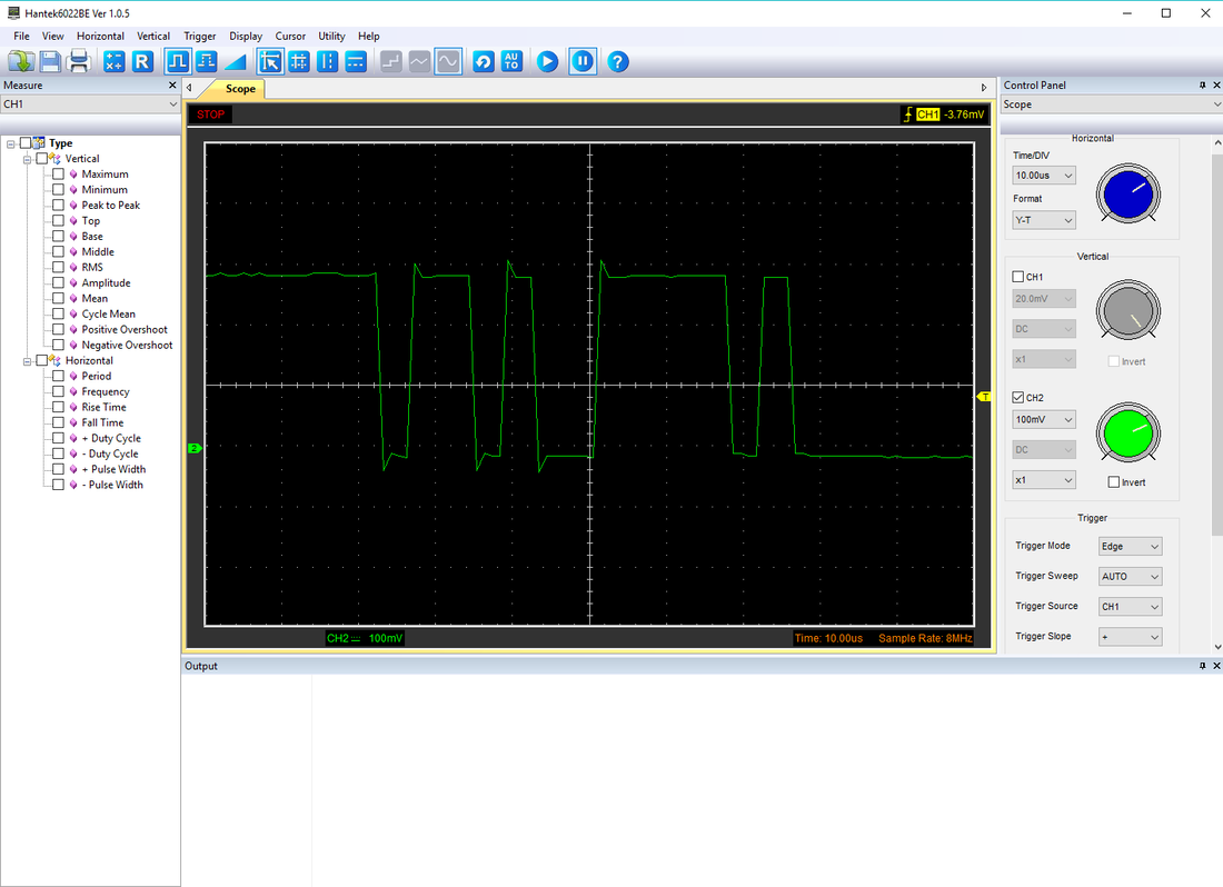
for example you could check an Arduino PWM signal with this tool and measure the duty cycle, voltage or if it is even working at all. I bought mine here This is a starting level device and it has it's limitation but it is cheap and will do the job. It does not have it's own display like and expensive, portable and professional ones, but it will rather connect to your computer via USB and you will see the signal over the computers screen when lunching the application that comes with it. Please check out this video to see it in action Also note that you can use the scope with the software provided or use the open source PulseView or the another great alternative is basicscope 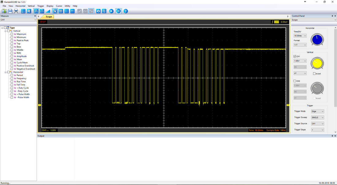
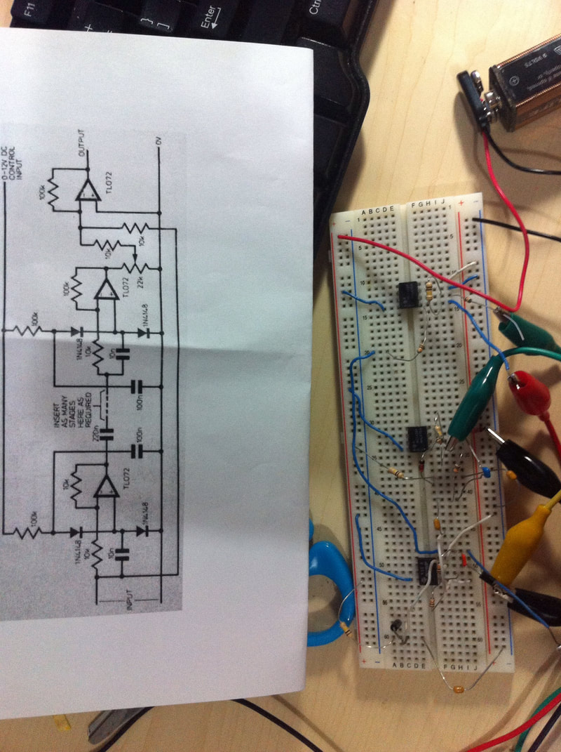
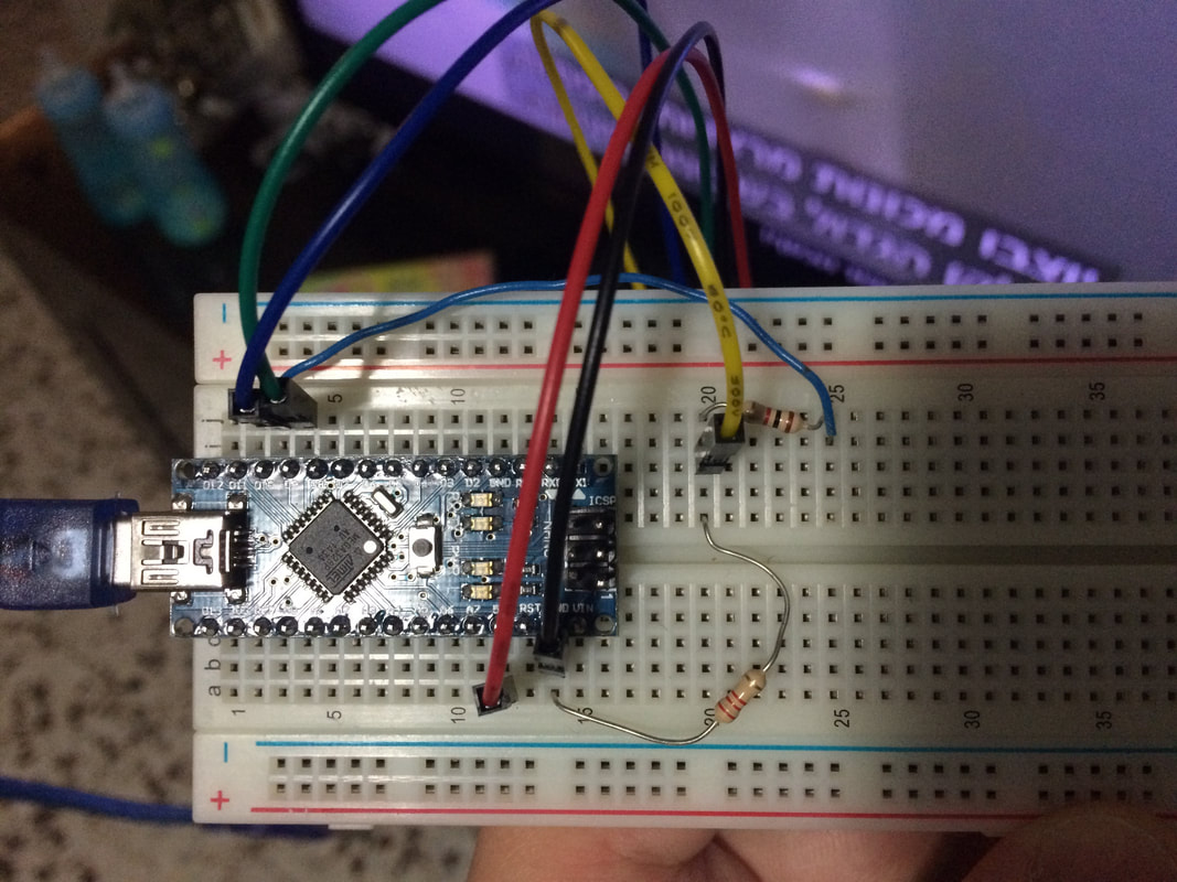
While building my SmartHomeDIY project I encountered a problem trying to use multiple SPI devices connected to the same Arduino.
Although the SPI bus should support multiple devices at the same time (toggling the Chip-Select line), this does not always work (mostly due to part using the bus not respecting the chip select or other configuration issues). So after reading for some time and experimenting I came up with the following solution. learn more about transistors here 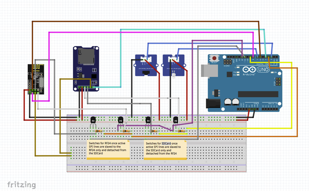
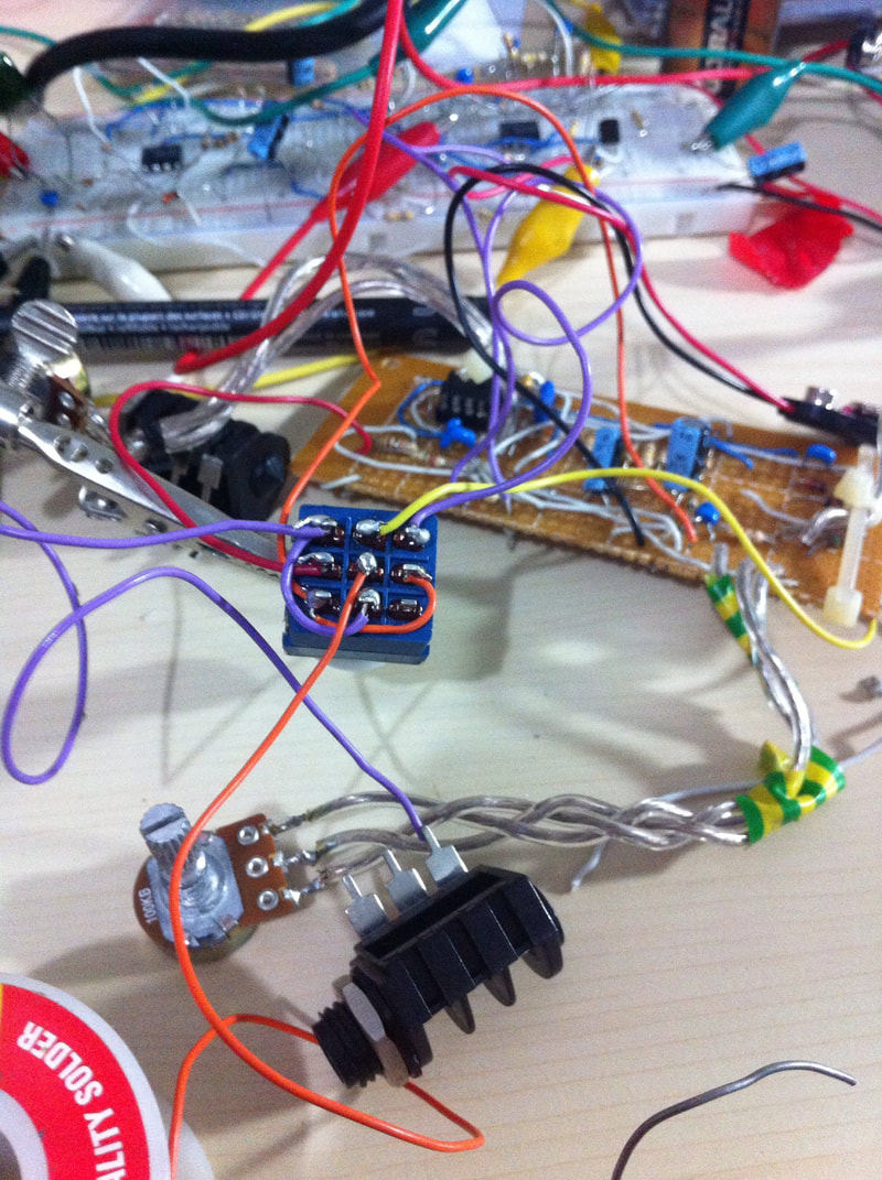
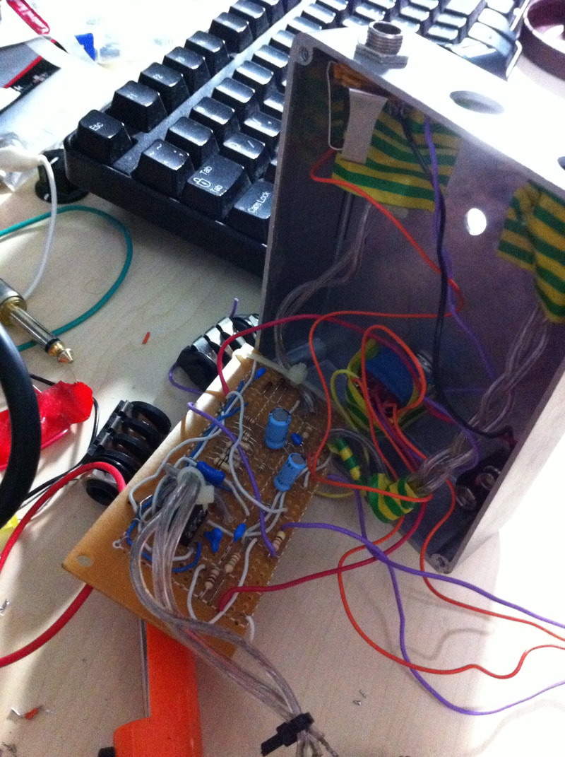
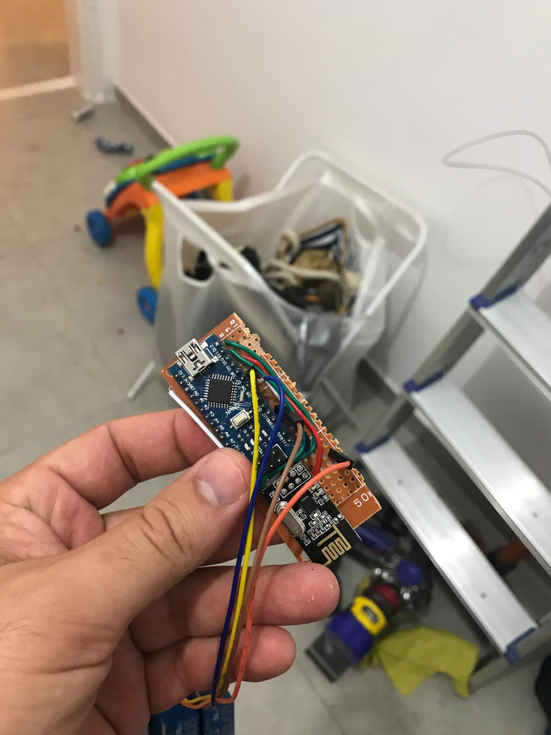
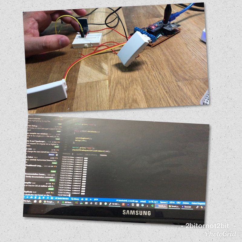
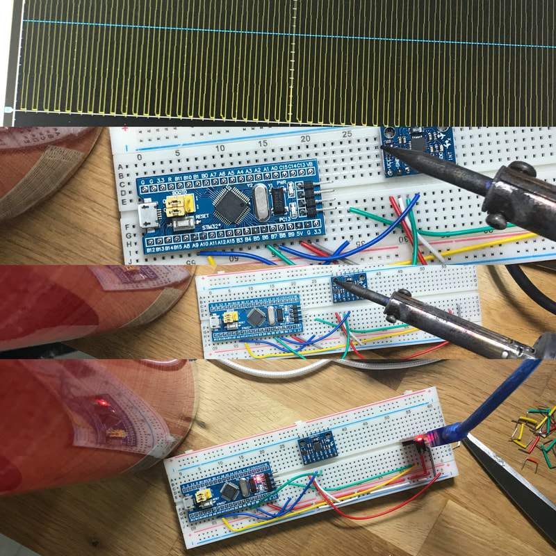
IR Station using multiple SPI devices.
The above station is an IR recorder and transmitter station.
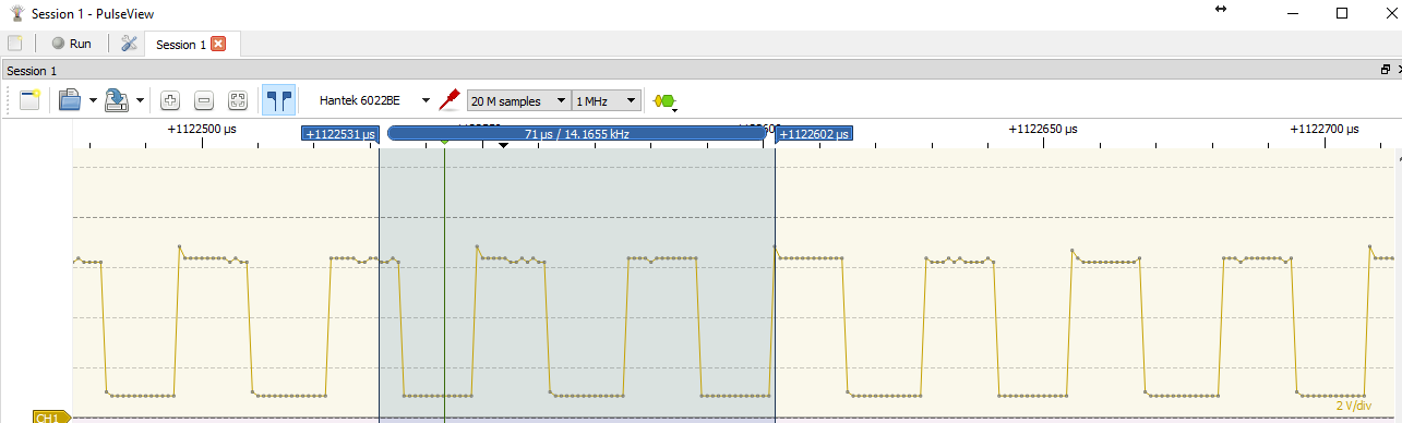
It can be set into recording state which then saved the recorded IR-in data into and SDCard connected over SPI. But when not in recording mode it will listen over the RF24 (also connected via SPI) for commands. Once a command is given it will try to send the IR code request (for example turn TV on) To do that it will again have to move to SDCard mode and read the previously recorded data and retransmit it over the IR out LED. So to solve this I have connected the SPI lines to couple of transistors/switches, They just CUT the lines of the component which is not being used at the moment and there for prevent the SPI lines collision. Attached is the code and hardware layout to do just that Note that it does not matter which type of project you have. You can always do the same transistor-switch trick to cut of the problematic SPI lines while using the others. A special note for the transistor configurations, It will not work if you design you transistor configuration as usually suggested, which means to set a logic level by design at the output of the transistor so that the base will toggle the out voltage (same as an amplifier). Instead I set the signal to go trough the transistor, which needed so testing to select the transistor which does not affect the actual signal (it will depend on the transistor type, spec and configuration...) So it took me some time to figure out the right transistor values and configuration. For trail and error I used this logic analyzer 8 logic lines or better yet one of these pro logic analyzers or one from ebay and there is also a very cool one which has 8 digital channels and one analog - perfect for beginners. I inspected the incoming signal and the outgoing signal to make sure the transistor does not temper with the incoming signal so everything will continue to work as expected (the transistor are transparent to the actual data) You could also try this Hantek 6022BE PC USB Digital Oscilloscope which is working perfectly on Window 10 environment. You could also get one on ebay You could also use this logic multiplexer [8 Channel Logic Level Converter Convert TTL Bi-directional] to do the same job which I have not tested yet. But I think my way is more fun! :) |


 RSS Feed
|
|
|