2BIT || ! 2BIT 👨‍💻
  • Home
  • Blog
  • About
  • Social
  • Affiliate ​Store
  • Home
  • Blog
  • About
  • Social
  • Affiliate ​Store

Arduino bootloader with OTA (over the air) support over nRF24L01

1/13/2018

 
As I was building my SmartHomeDIY platform (OpenSource) one of the first things I was looking for (except of debug tools and board), was a bootloader for Arduino which supports over the air flashing of the internal sketch.
I needed this because I was about to mount all the Arduino board inside my wall, and I did not wanted to take them apart every time I had a bug.
So the way to go, is over the air (OTA), which Arduino does not supports out of the box, so lets learn how to do exactly that.
In order to get OTA working on your Arduino You will need to flash on it a special bootloader that support OTA, but not just any boatloader, you will need one specific to the type of your communication board - in my case, RF24,

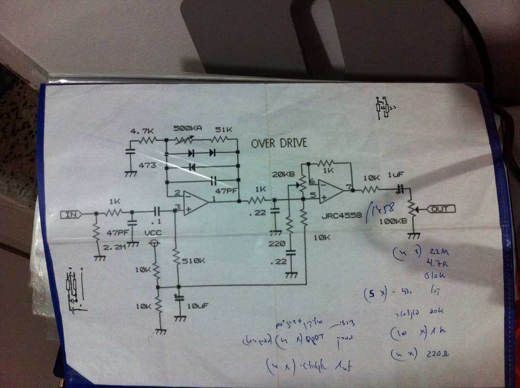
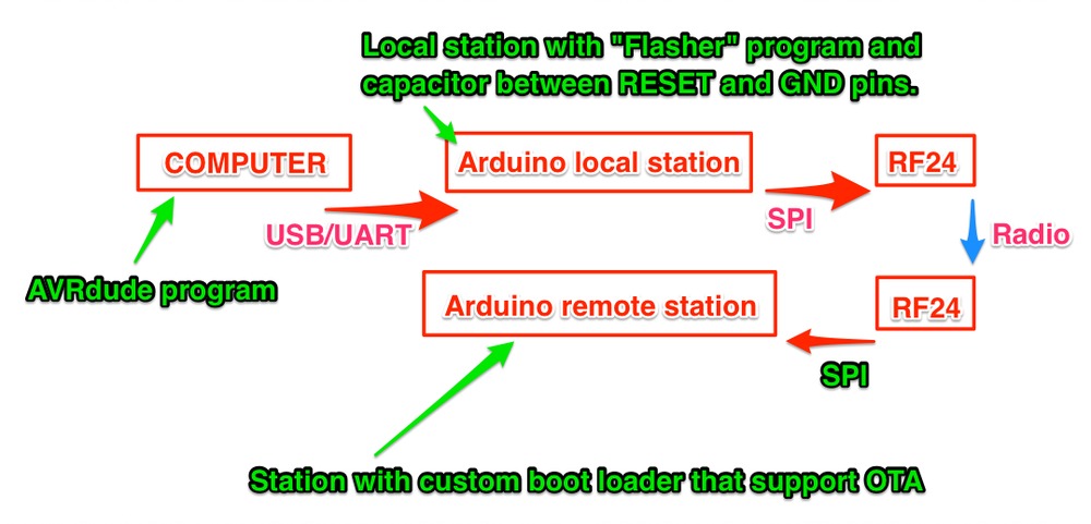
If you do not know what is a bootloader please read here.

I wanted this bootloader with work with the rf24 [1] radio board - which you can buy [here]
You will need an Arduino library which support this board which you can find here
I am using Mirf and you will probably need to use it to if you will take my code

So, to start with I needed an open source code that has a modified version of the original Arduino bootloader or a custom basic bootloader like this one.

And I found one on github that does just that and it is called optiboot-nrf24l01
which is a fork of this git

What this code does is not too complicated.
When you flash a program using the Arduino IDE what that is actually happening is that the USB driver (you Arduino board is probably connected via USB) is resting the Arduino in to a bootloader state (think of the bootloader as an operating system or a bios)
Then the bootloader waits for couple of fractions on the UART to receive a spesific data (bytes) which tells it to start the flashing process,
If it gets it then he will flash and override the sketch that is already there.
if it does not get anything (timeout) it will just start the sketch that is already there and run it in a loop.
​
So what we need is to:
  1. Find a way NOT TO BE RESETED BY THE USB PORT.
  2. Get the bytes (sketch data) from the computer
  3. Forward the bytes to the remote station
  4. Capture the bytes on the remote station
  5. Override the sketch on the remote station.


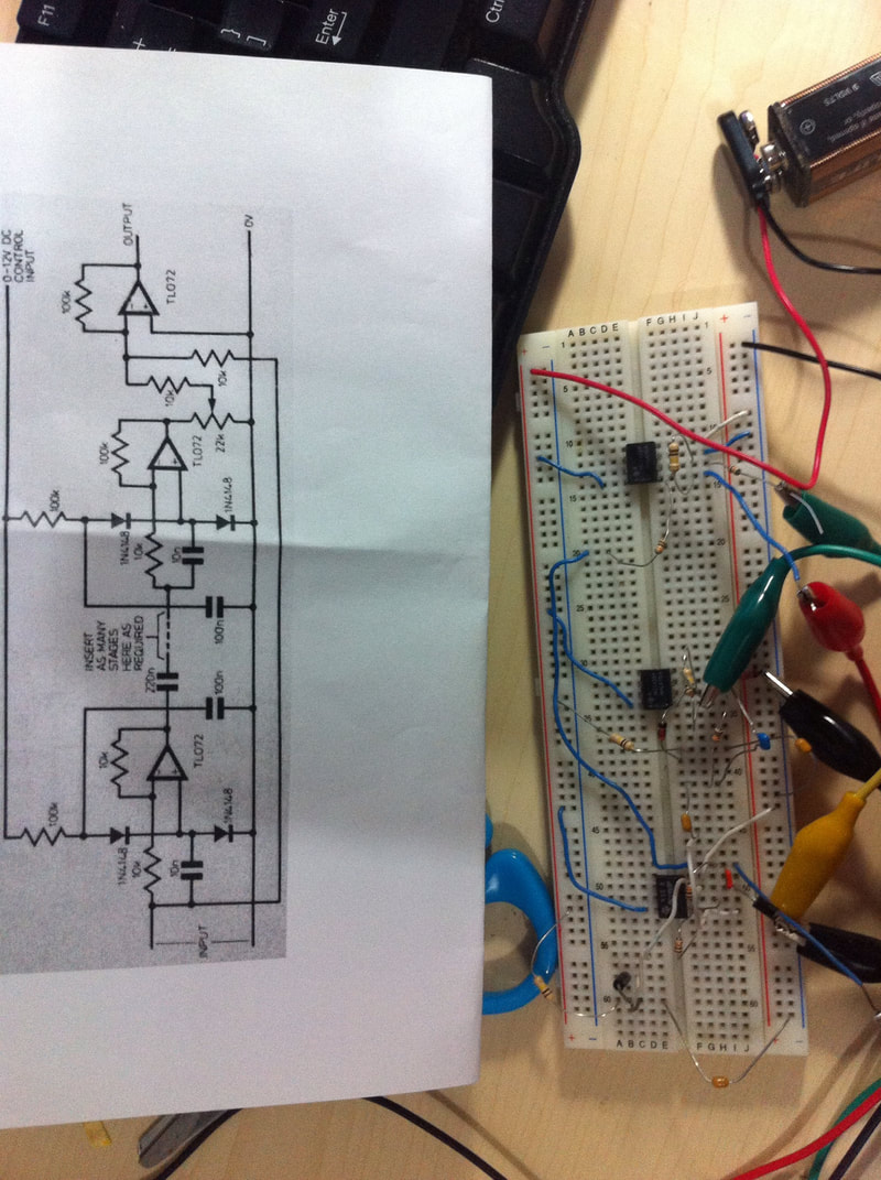
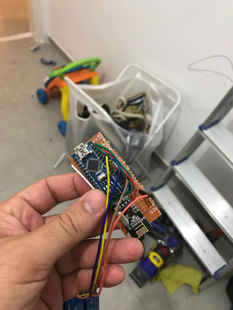
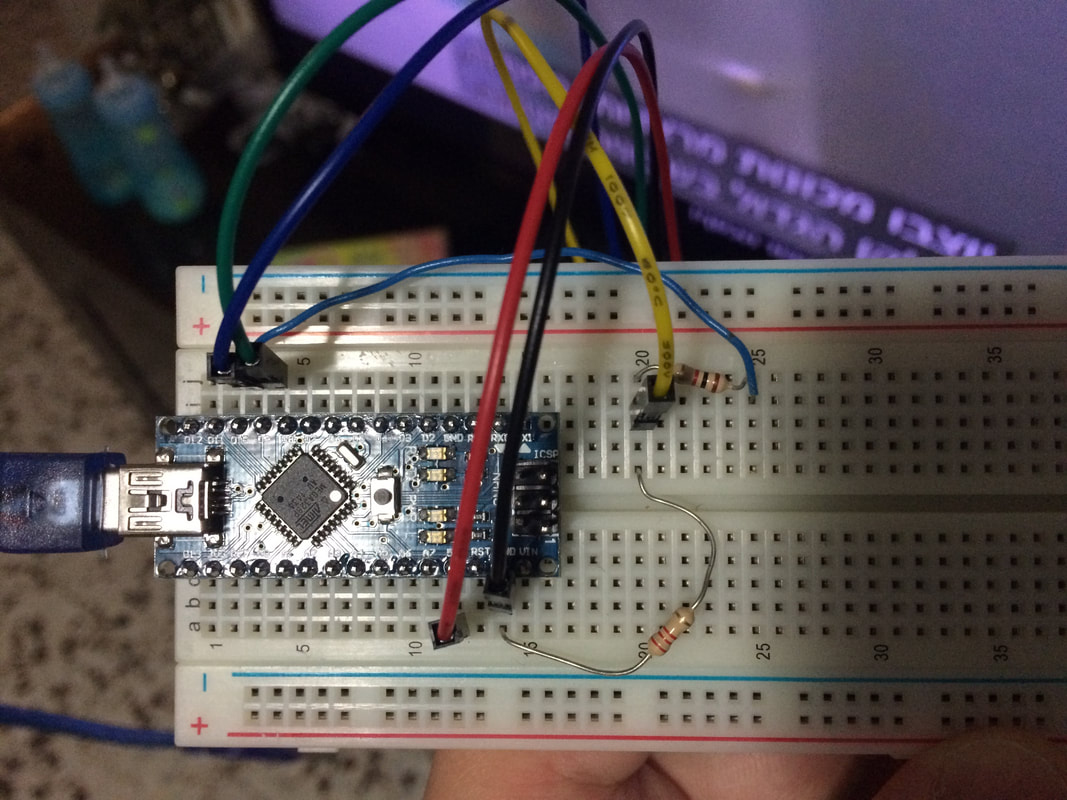
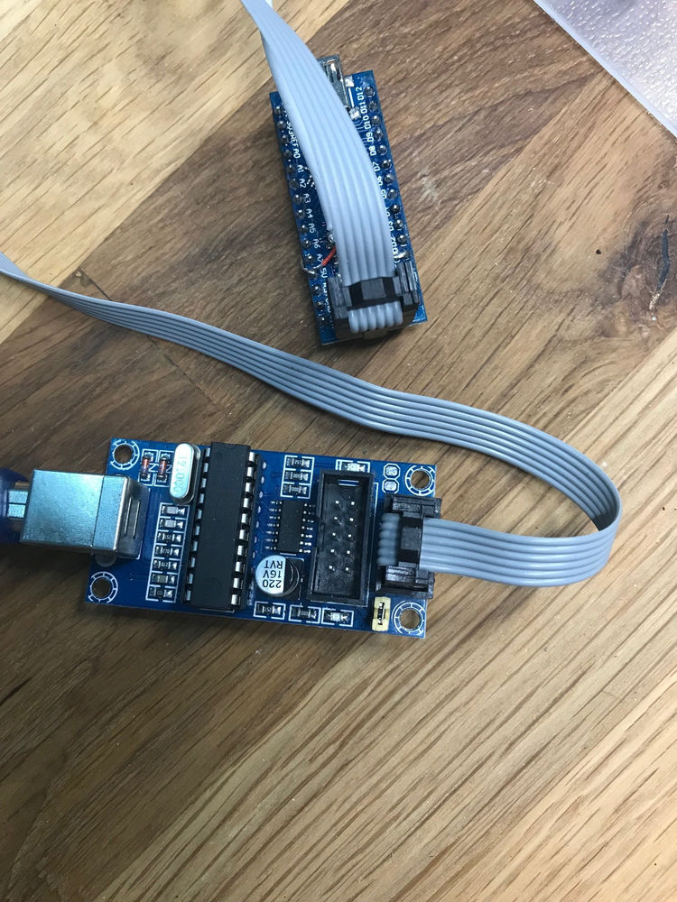
The code over optiboot-nrf24l01 is the one responsible of capturing the bytes on the remote station and overriding the sketch there.

But we still need a
local flasher program which was also forked and modified by the same guy here.

This code is responsible to get the bytes (sketch data) from the computer and forward theme to the remote station.

The problem that I had is that every time I was trying to flash the remote station I was eventually flashing the local station.

This is where point 1 is getting into the picture and it took me some time figure it out and find the right solution
what you will have to do is put a 10uF capacitor in between the RESET pin on the Arduino and the GND pin
This way when ever the USB driver is trying to reset the board it will fail but will continue with the flashing process.
Picture
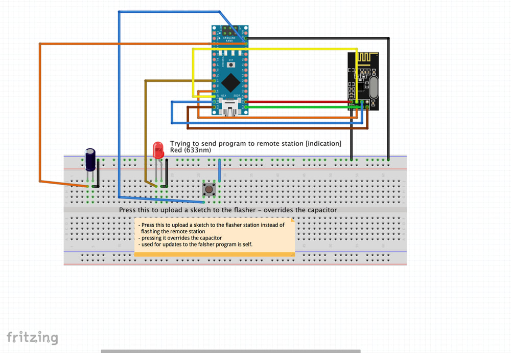
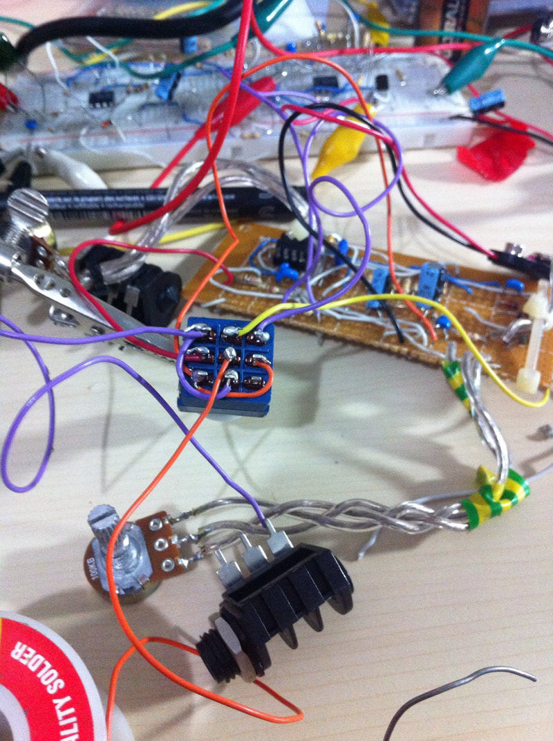
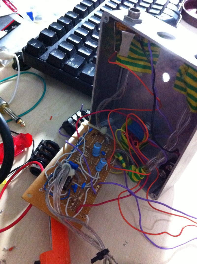
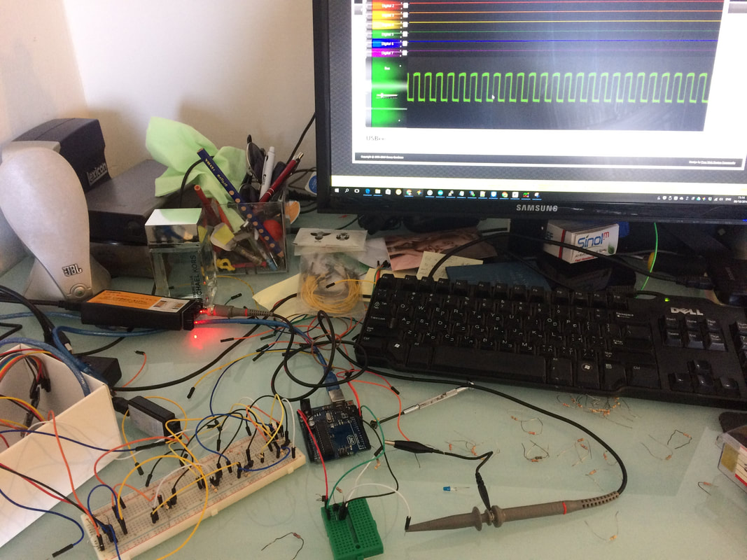
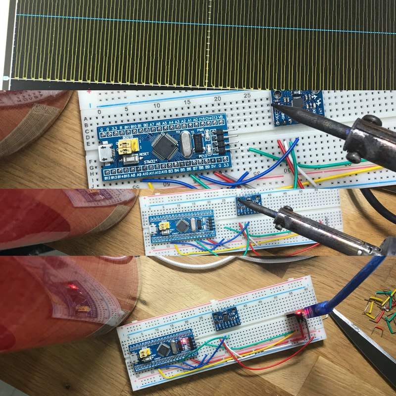
​The above is the hardware setup as I was using it, note the 10uF capacitor.
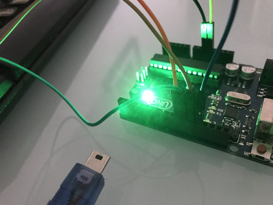
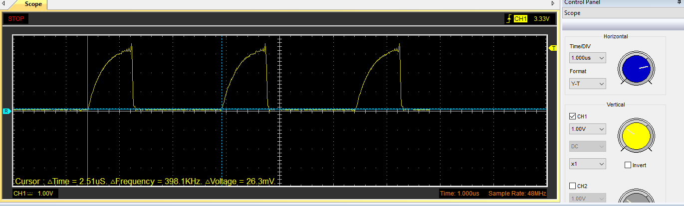
The led here is just for debugging.
I used it to make sure I am getting the bytes and was really thing to forward them to the remote station (write the to the rf24 registers over SPI).
If you need the debug code you can get it here

Using AVRDude to flash the bootloader

Once you have the above local station connected you will need to flash the remote station with the custom bootloader who has the OTA support (note that the remote station hardware configuration configuration is actually the same as the above except the capacitor)
Picture
First this is to compile the bootloader once you have that you can run avrdude commands against it in order to flash the remote station. by the end of this process you should have an bootloader.hex file.

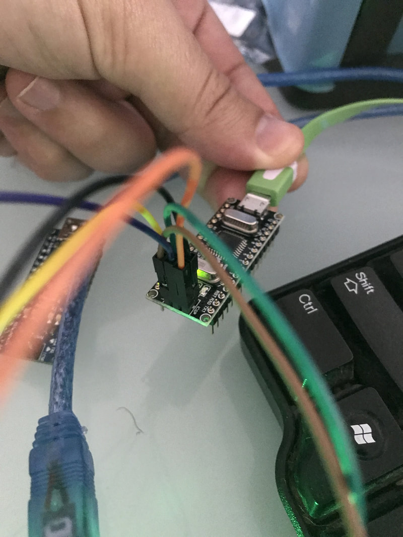
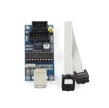
To flash the ota-bootloader hex file you will need 2 commands and an AVR Programmer,
You can probably use another Arduino to burn the bootloader but using the programmer is much more convenient

Just connect the AVR Programmer to the computer and to the Arduino header like this
AliExpress.com Product - USBTiny USBtinyISP AVR ISP programmer bootloader Meag2560
Picture

Flashing commands for avrdud

Code Editor

Note the 0xDA on the first command - it will not work without it.
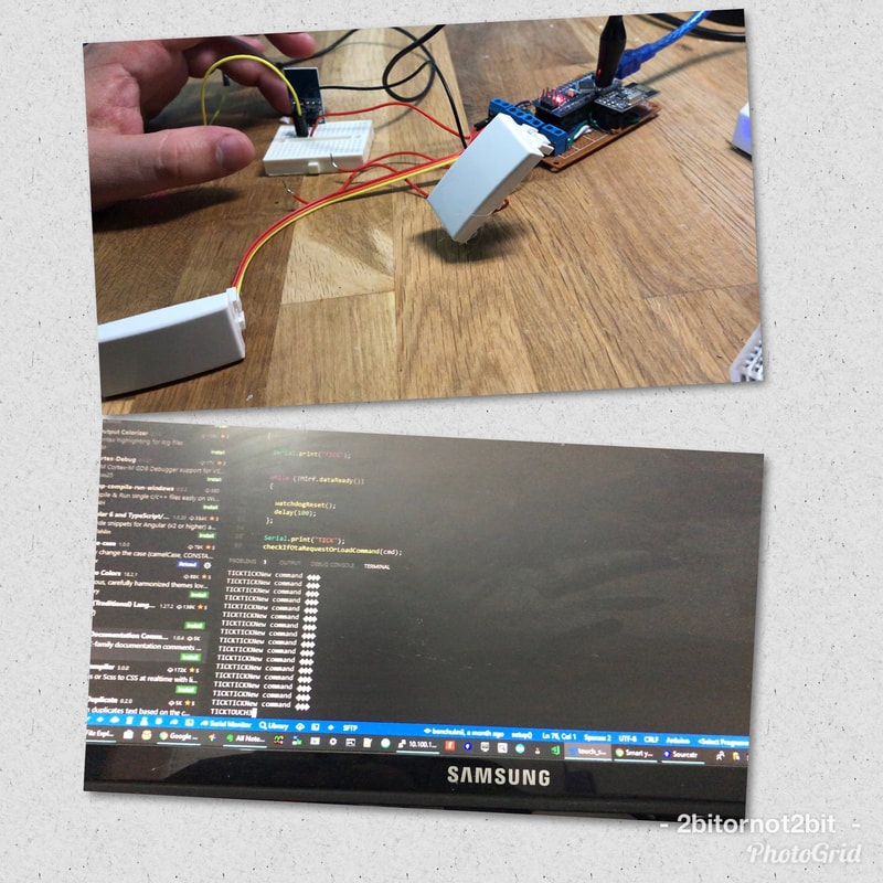
optiboot_atmega328_without_watchdog.hex is the compiled bootloader hex file.

Btw, I compiled my bootloader without the watchdog option (by default it will reset into bootloader every 10 sec or so to allow remote bootloading automatically, in my code I just added to my sketch the option to reset the Arduino when it gets a specific command) - read more here

When this is done you should see something like that:
Picture
Picture
Picture

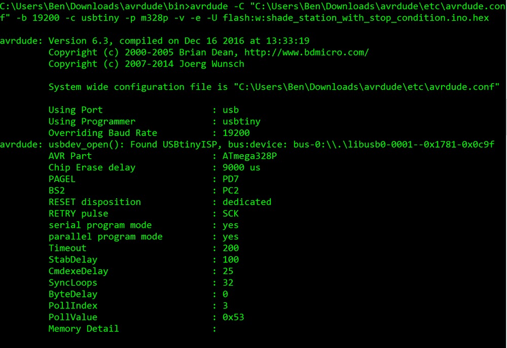
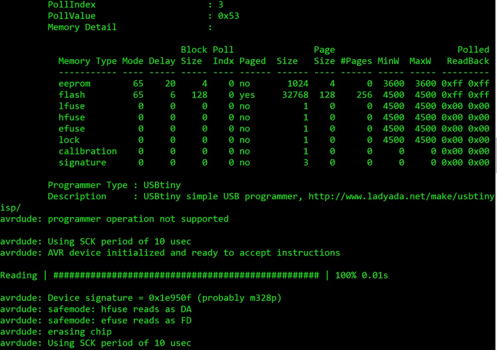
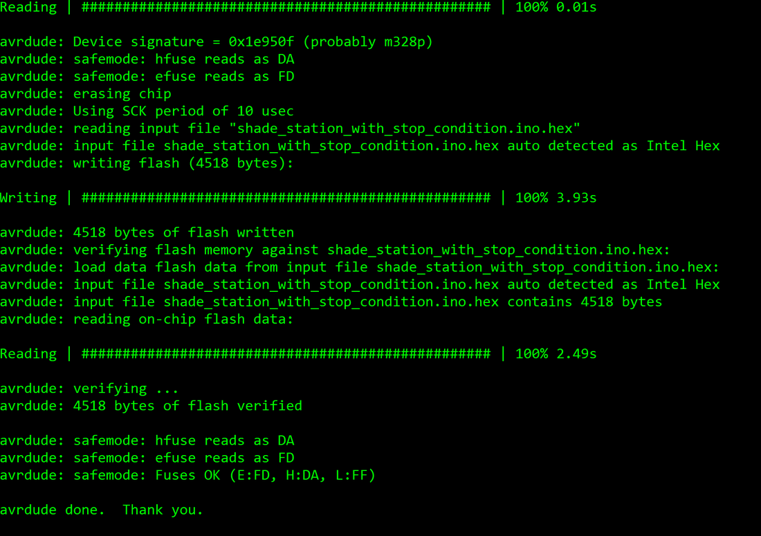
Great! now our remote station is ruining our new bootloader!

​All that is left out is to run an avrdude command to flash the local station as if it the remote one - we will just flash our hex file (the same way Arduino IDE does behind the scenes).

​When you compile you sketch on Arduino IDE it just puts it on a directory on your computer
I usually just copy it to my avrdude directory and flash it from there.
To read more about getting the sketch hex file read here.
If you need more here with flashing the boot loader check this.

The most important things to remember are:

  1. The capacitor for the local station - more info about disabling reset from USB here
  2. Flashing commands - the 0xDA flag
  3. use my code for debug with LEDs for the bootloader and the flasher if it does not work for you - it will light-up some LEDs to let you know packets are flowing over the air. if need to learn how to turn led on and off in bootloader mode, read this reference about Port Registers manipulations.
  4. In my case the sketch that I needed was using RF24 communications as well, so I needed the boot loader and the sketch to use the same RF24 library so I used mirf24 lib . that way once the sketch is loaded so it will be able to reset in to boot loader and flash (registers state on the rf24 board stays the same and this make the process work better).
  5. Note that timing here is a problem so you might need to rest the remote station manually for trail and error with the reset button on the remote Arduino station.

Finally check these links to get the Hardware and the tools needed to get the job done:

Arduino board: http://s.click.aliexpress.com/e/ZBeuJey
USBtinyISP AVR ISP programmer bootloader: http://s.click.aliexpress.com/e/aUvjA2F

All the Arduino schemes attached here where generated with the cool tool:
http://fritzing.org/home/

Hope it will serve you all well,
Fill free to comment or email me with questions.
Please subscribe my Youtube channel.
And my facebook page.

AliExpress.com Product - Free shipping 1pcs/lot New FT232RL FT232 USB TO TTL 5V 3.3V Download Cable To Serial Adapter Module For Ardui USB TO 232
MODaly
1/30/2018 05:32:09 pm

If you have multiple clients with different tasks, how do you address which one you are sending the OTA to?

For example: You have a light switch, a coffee pot, and a door lock each as a remote controlled device controlled by their own Arduino.
How do you keep the door and light from thinking they are coffee pots after you adjust the code to the coffee pot?

2bitornot2bit - benchuk
1/31/2018 05:30:48 am

Hi MODaly,
Thanks for the question.
Each remote station has an address - the RF24 support 3 byte to 5 byte address space.
all my remote stations have different address for example light switch in your example would be "001" coffee pot will be "002" (in this example 3 bytes addressing).
Each time I want to update a different station I update the local station with the remote station address, if you will look at the startup code of the flasher station (the local one) you will see that it load on startup it's own address (first 3 bytes from eeprom) which are not used in the flasher station case) and the required remote station address from the next 3 bytes of the eeprom.
the way to put this address there are:
1. on startup code write to the eeprom the address you wish - meaning hard-coded - you would need to uploaded a new sketch to the local station each time,
2. use avrdude to write these 6 bytes to the eeprom:
$ avrdude -F -p atmega328p -P /dev/ttyUSB0 -c arduino -b 115200 -U eeprom:w:0x30,0x30,0x31,0x30,0x30,0x30:m
the importatn part with the "eeprom:w:0x30,0x30,0x31,0x30,0x30,0x30:m" the rest it up to the burner type and ofcoursse you need to udpate 0x30 to what ever address you want - 0x30 in the ASCII table is "0" - so in this example the local station address is "001" and the remote one is "000"

Phan Tuấn
8/19/2018 06:48:32 pm

Hi
Your OTA support over RF24 is very interesting. I'am trying OTA by following your path in https://www.2bitornot2bit.com/blog/arduino-bootloader-with-ota-over-the-air-support-over-nrf24l01 but without success.

I use 2 Arduino Uno to transmit (Arduino local station) and receive (Arduino remote station).
CE -> PIN9, CSN -> PIN10, capacitor like instructions.

Arduino remote station: I burn bootloader "optiboot_atmega328.hex" from https://github.com/nicolas-schurando/optiboot-nrf24l01/tree/master/avr/bootloaders/optiboot-nrf24l01
I use two command in cmd win10:
C:\Program Files (x86)\Arduino\hardware\tools\avr\bin>avrdude -C "C:\Program Files (x86)\Arduino\hardware\tools\avr/etc/avrdude.conf" -b 19200 -c arduino -p m328p -cstk500v1 -PCOM3 -v -U efuse:w:0xFD:m -U hfuse:w:0xDA:m -U lfuse:w:0xFF:m -F

C:\Program Files (x86)\Arduino\hardware\tools\avr\bin>avrdude -C "C:\Program Files (x86)\Arduino\hardware\tools\avr/etc/avrdude.conf" -b 19200 -c arduino -p m328p -cstk500v1 -PCOM3 -v -U flash:w:C:\Users\TRANPH~1\Downloads\optiboot_atmega328.hex  -U lock:w:0x0F:m

It was reported as ok

Arduino local station: I upload "optiboot-nrf24l01-flasher.ino" from https://github.com/nicolas-schurando/optiboot-nrf24l01-flasher
after that I upload blink_led to Arduino remote station by command:
C:\Program Files (x86)\Arduino\hardware\tools\avr\bin>avrdude -C "C:\Program Files (x86)\Arduino\hardware\tools\avr/etc/avrdude.conf" -b 19200 -c arduino -p m328p -cstk500v1 -PCOM4 -v -U flash:w:C:\Users\TRANPH~1\AppData\Local\Temp\arduino_build_920680/BlinkWithoutDelay.ino.hex 

But I always get the message:
avrdude: stk500_getsync() attempt 1 of 10: not in sync: resp=0x1e
avrdude: stk500_getsync() attempt 2 of 10: not in sync: resp=0x66
avrdude: stk500_getsync() attempt 3 of 10: not in sync: resp=0x98
avrdude: stk500_getsync() attempt 4 of 10: not in sync: resp=0x66
avrdude: stk500_getsync() attempt 5 of 10: not in sync: resp=0x60
avrdude: stk500_getsync() attempt 6 of 10: not in sync: resp=0x7e
avrdude: stk500_getsync() attempt 7 of 10: not in sync: resp=0x86
avrdude: stk500_getsync() attempt 8 of 10: not in sync: resp=0x7e
avrdude: stk500_getsync() attempt 9 of 10: not in sync: resp=0x00
avrdude: stk500_getsync() attempt 10 of 10: not in sync: resp=0x18

and nothing happened.

Please tell me where is my fault. Thank u so much

Frank
12/3/2018 01:06:34 pm

Hi, I have the same issue; not able to get a blink-sketch to the remote station.AVRDUDE reports retry for 10 times.
Did you already find or got your answer? Please share as I also would like to have this to work!

Thanks!

BR,
Frank

Mateusz
2/18/2019 10:13:45 am

I also have the same issue.
:-(

Zoe link
12/25/2020 12:29:26 am

Thanks, great post


Comments are closed.
    AliExpress.com Product - Free shipping! Microcontroller learning kit starter and proficient 24 interactive lessons for arduino
    View my profile on LinkedIn

    Categories

    All
    ARDUINO
    ELECTRONICS
    Embedded
    Raspberry Pi
    STM32F103C8T6
    TOOLS

    RSS Feed

Don't forget 📝

If you like what your read and it helped you trough the development and professional 
​growing 
​journey, please subscribe and share.

Get in touch 👇