|
As part of my SmartHomeDIY project (open source), I need as small and efficient server which could also talk to my Arduino stations that are using RF24 module, so for the rescue came my Raspberry PI and it's serial GPIO pins.
All of my Arduino stations are talking to each other with the RF24 module (connected via SPI) and I needed a fast lightweight server (and small in size) to talk to that network.
I wanted to use the PI to do that job and I knew I could use it's GPIOs as serial (usually used for console logging in Hardware development stages) So I figured why not connect a serial device to the PI GPIOs and through this device I will talk to my network. So I figured up the following setup 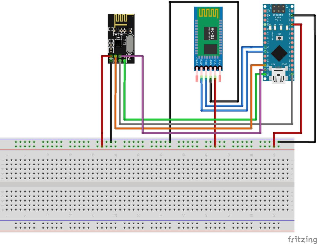
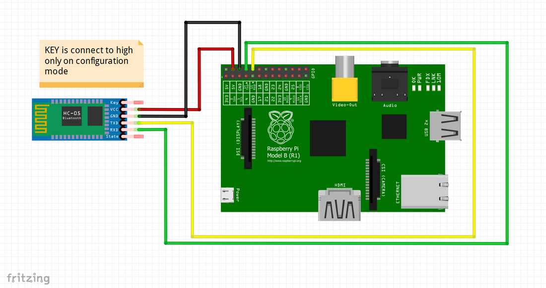
I connected the PI to a serial BT device called Bluetooth HC-05
This device can talk via serial and forward everything to the other side BT device which is connected to an Arduino which in turn checks the commands and forward these commands to the specified Arduino station via the RF24 module, we will talk about the protocol and the BT device configuration in a moment. 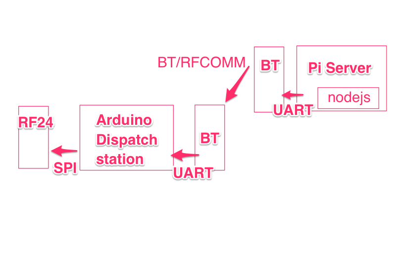
nodejs, pi and serial
To use the PI serial you will first need to disable PI console prints to serial, to do that go here
To know more about pi serial read here If cannot disable serial for pi read more here As a summary here is what you will have to do:
1. download a utility
2. disable serial
3. check status
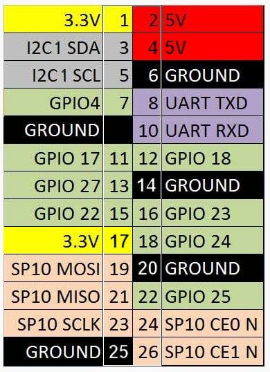
You will need to connect the bluetooth module to the PI GPIOs as shown above - here is a closeup
BE SURE TO DOUBLE CHECK BECAUSE THE PI DOES NOT HAVE PROTECTION CIRCUITRY - YOU CAN BURN YOUR PI FOREVER! 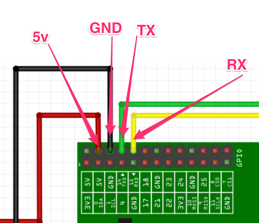
Note that there are at least 2 types of revision for the PI board - so make sure which one you have - each one has a different GPIO layout
Configuring the BT modules to talk to each other
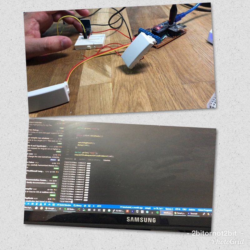
To config the 2 BT modules to talk to each other and act as an over the air UART we will need to enter the AT command configuration mode, to do that we will give power to HC-05 while key pin is connected to Arduino pin (9) and pin (9) is already HIGH (or other pin you wish to use or any HIGH level source).
After all these commands the BT modules should be binded and auto connect always. For more AT Commands info look: After all the configurations, if everything is fine, the BT modules will blink at a slower rate, which indicates that the modules are in sync and connected to each other. note that every time you will reset the modules they will blink fast until connected to each other and in sync, I am using that indication a lot, for example to see if the modules are in range when installed in my house walls. talking to the serial from node
After everything is connected and configured all we have to do is to send the data (commands) in my case through the serial (UART) port to the dispatch station
To do that will we have to use node serial module https://www.npmjs.com/package/serialport Install it as any node module. And here is an code example how to use it
Every command that we will send from this serial site will go through BT module and received on the other BT module and the Arduino on the dispatch station side will received that data as any other serial data, from there that station can parse that and forward it via SPI to the other stations
Here is the code for the dispatch station. Important parts of the code are highlighted here.
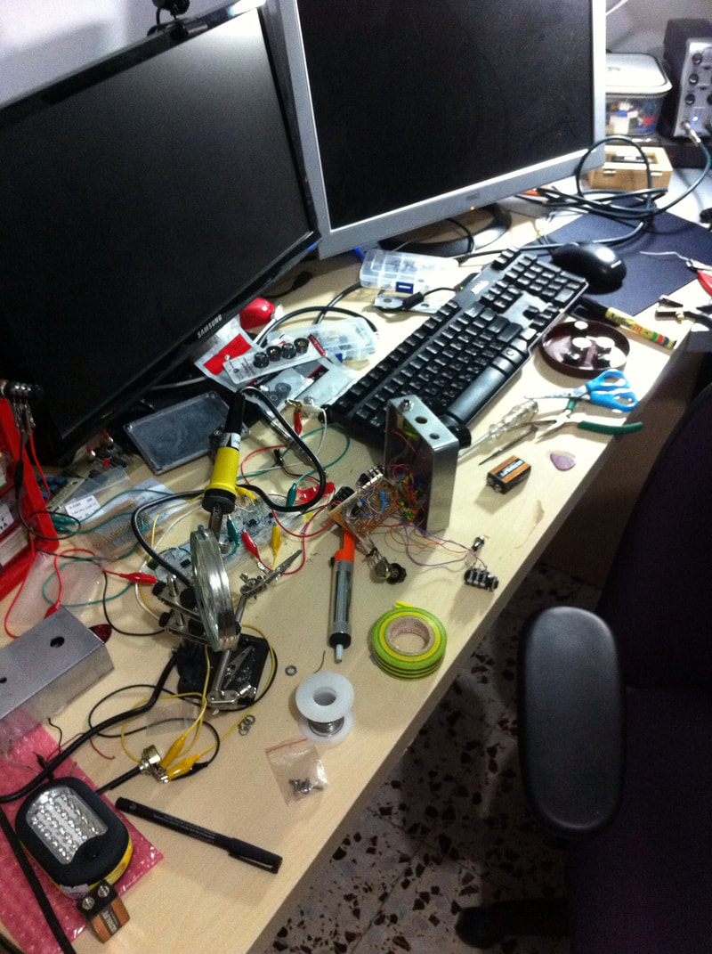
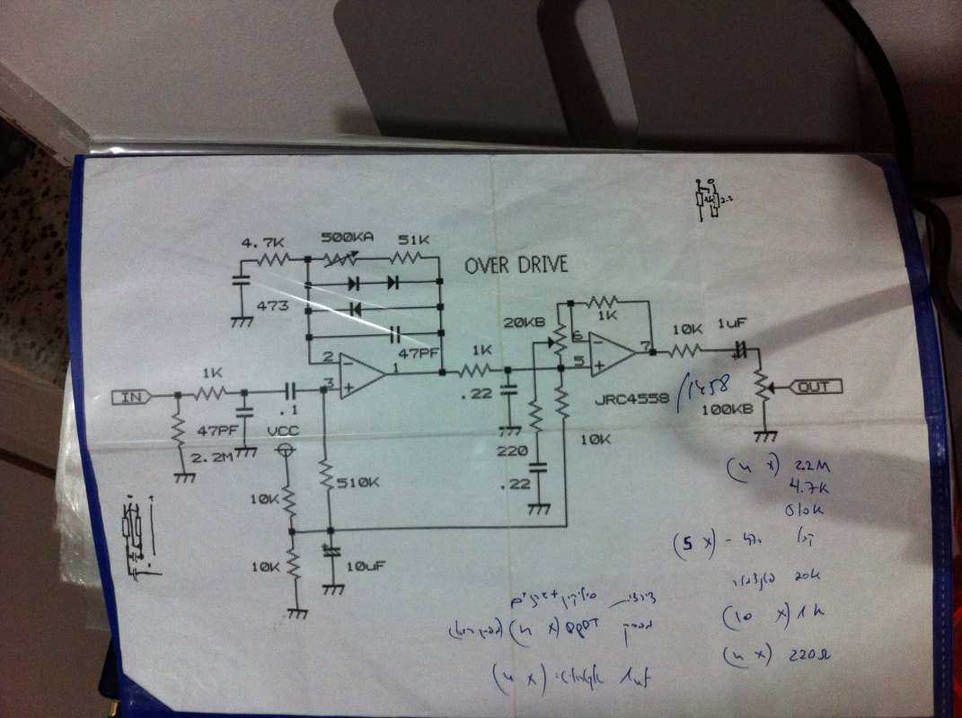
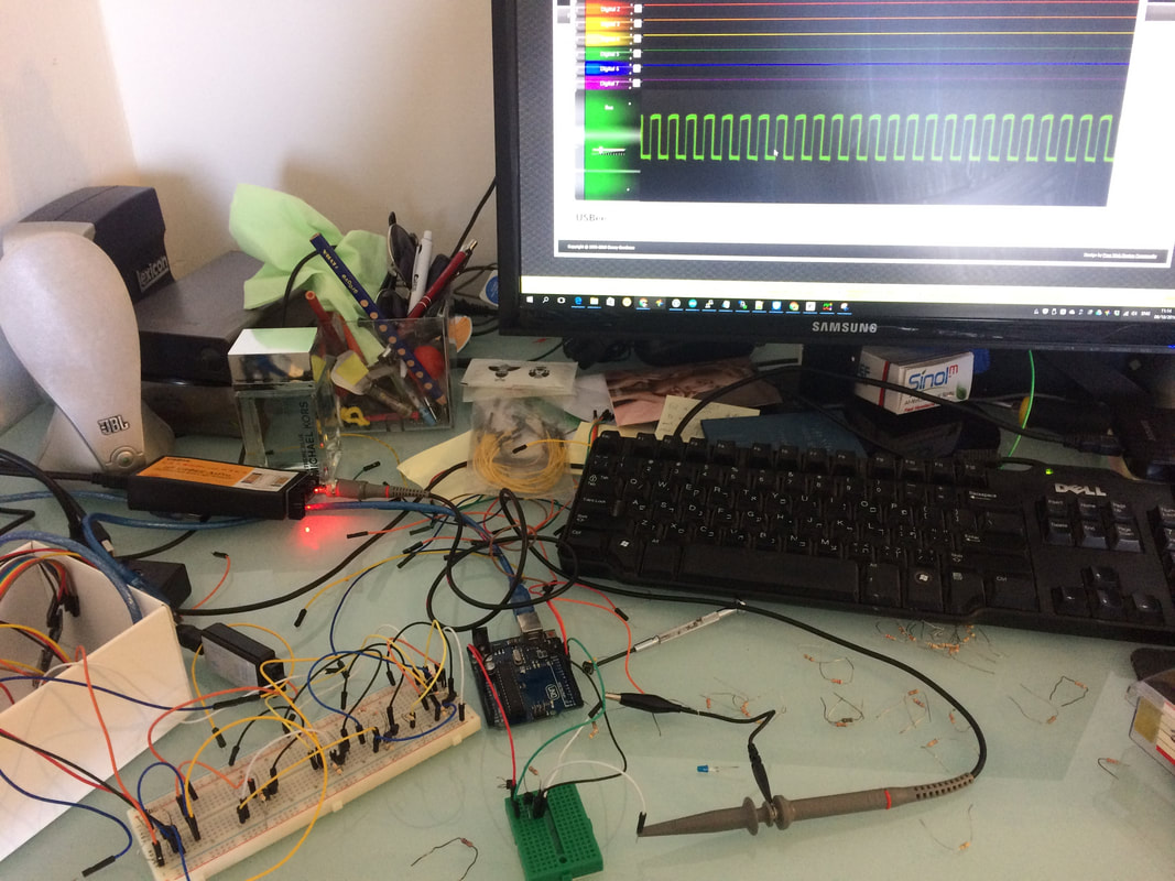
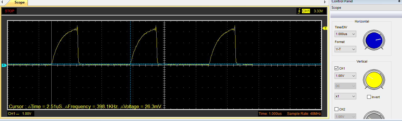
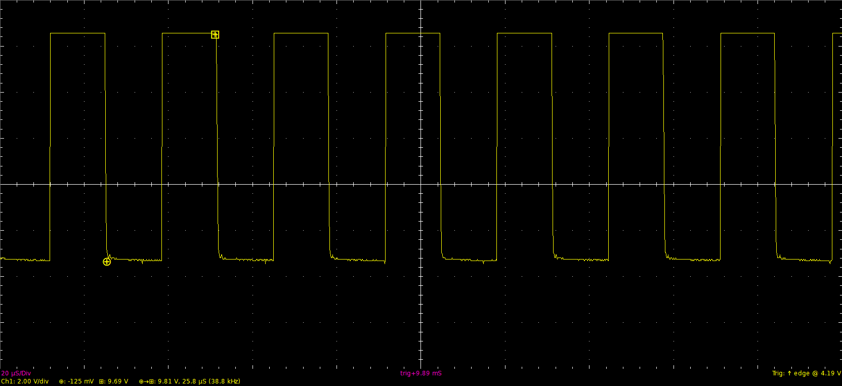
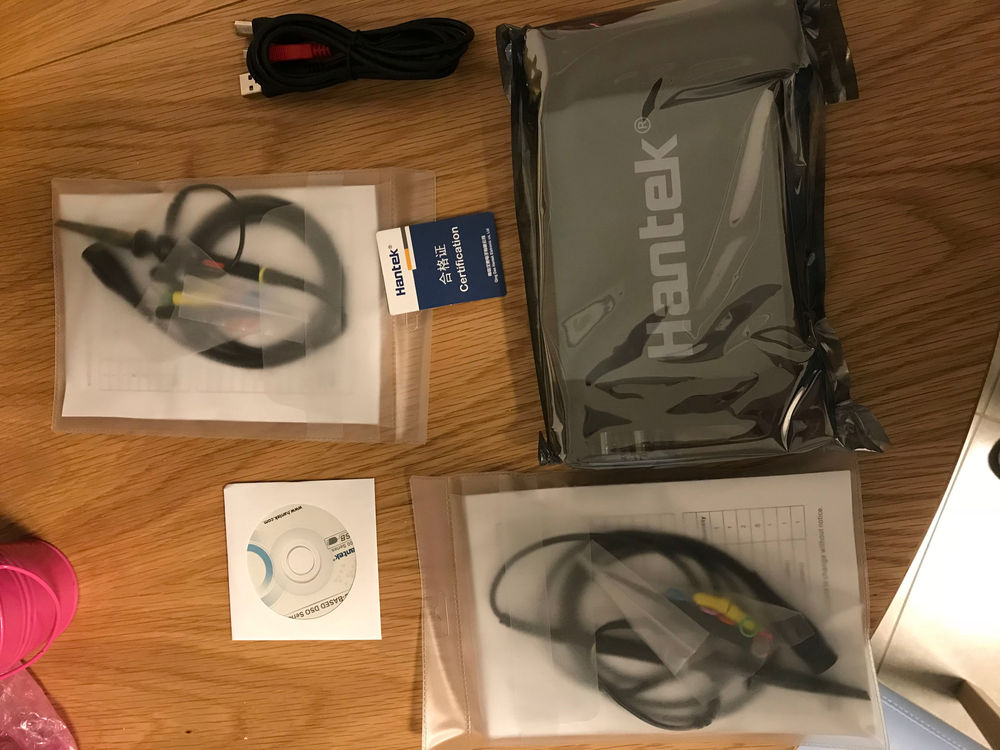
To trail and error with Arduino sketchs you will need some tools, one of them is an oscilloscope, lets learn the basics of this important tool.
An oscilloscope is a debugging tool for electronics circuits where you can prob any point and check out the signal in watch it in real time (voltage over time)
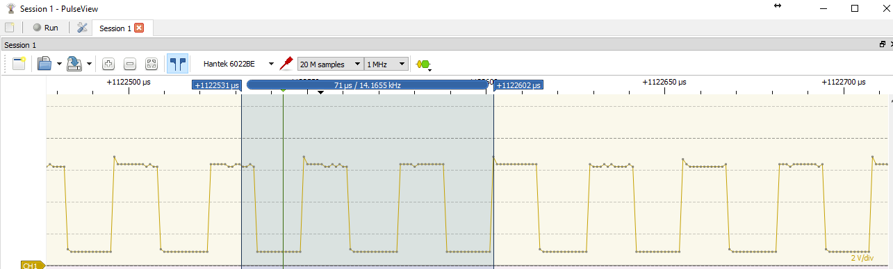
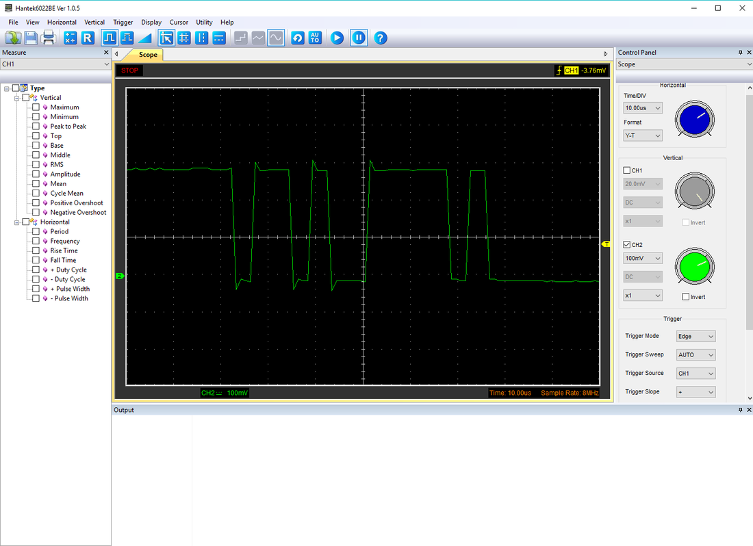
for example you could check an Arduino PWM signal with this tool and measure the duty cycle, voltage or if it is even working at all. I bought mine here This is a starting level device and it has it's limitation but it is cheap and will do the job. It does not have it's own display like and expensive, portable and professional ones, but it will rather connect to your computer via USB and you will see the signal over the computers screen when lunching the application that comes with it. Please check out this video to see it in action Also note that you can use the scope with the software provided or use the open source PulseView or the another great alternative is basicscope 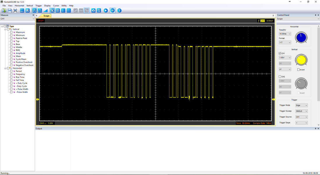
As I was building my SmartHomeDIY platform (OpenSource) one of the first things I was looking for (except of debug tools and board), was a bootloader for Arduino which supports over the air flashing of the internal sketch.
I needed this because I was about to mount all the Arduino board inside my wall, and I did not wanted to take them apart every time I had a bug. So the way to go, is over the air (OTA), which Arduino does not supports out of the box, so lets learn how to do exactly that.
In order to get OTA working on your Arduino You will need to flash on it a special bootloader that support OTA, but not just any boatloader, you will need one specific to the type of your communication board - in my case, RF24,
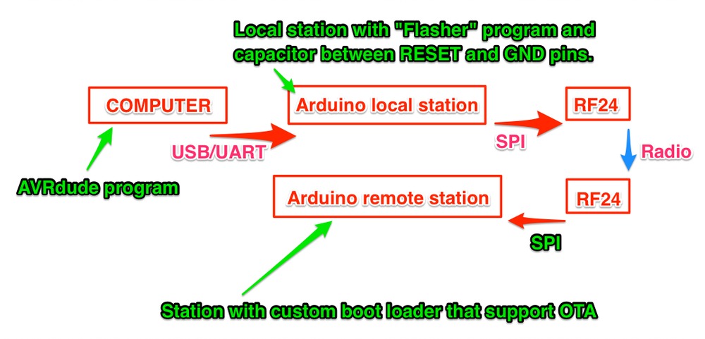
If you do not know what is a bootloader please read here. I wanted this bootloader with work with the rf24 [1] radio board - which you can buy [here] You will need an Arduino library which support this board which you can find here I am using Mirf and you will probably need to use it to if you will take my code So, to start with I needed an open source code that has a modified version of the original Arduino bootloader or a custom basic bootloader like this one. And I found one on github that does just that and it is called optiboot-nrf24l01 which is a fork of this git What this code does is not too complicated. When you flash a program using the Arduino IDE what that is actually happening is that the USB driver (you Arduino board is probably connected via USB) is resting the Arduino in to a bootloader state (think of the bootloader as an operating system or a bios) Then the bootloader waits for couple of fractions on the UART to receive a spesific data (bytes) which tells it to start the flashing process, If it gets it then he will flash and override the sketch that is already there. if it does not get anything (timeout) it will just start the sketch that is already there and run it in a loop. So what we need is to:
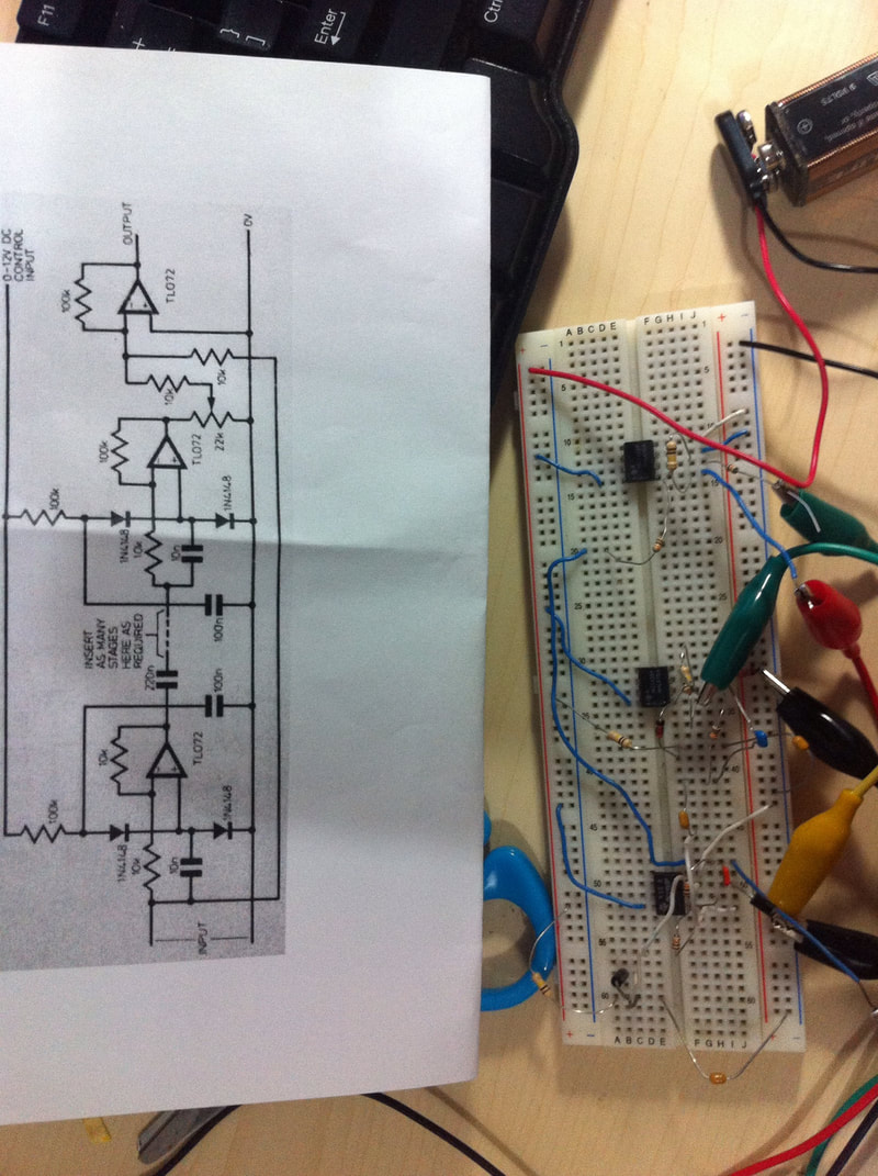
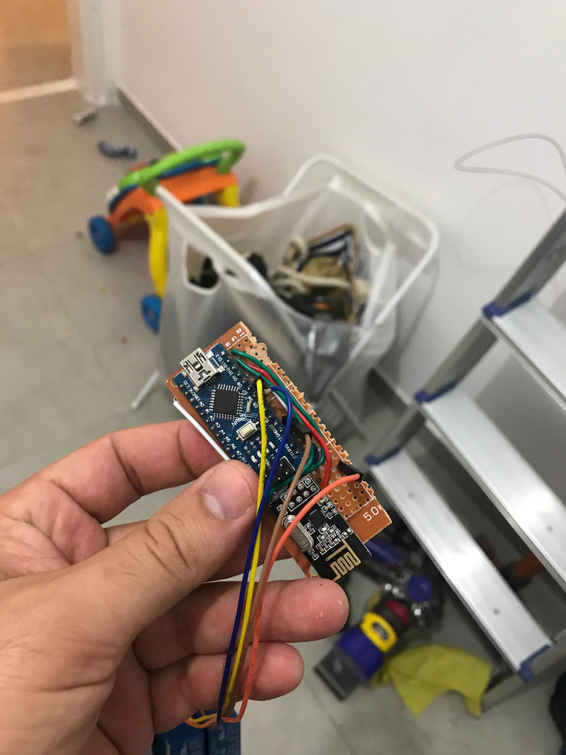
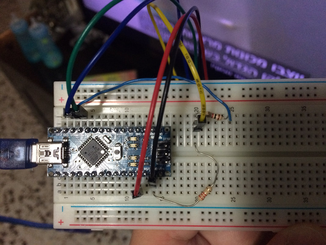
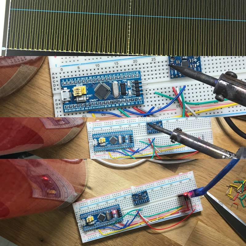
The code over optiboot-nrf24l01 is the one responsible of capturing the bytes on the remote station and overriding the sketch there. But we still need a local flasher program which was also forked and modified by the same guy here. This code is responsible to get the bytes (sketch data) from the computer and forward theme to the remote station. The problem that I had is that every time I was trying to flash the remote station I was eventually flashing the local station. This is where point 1 is getting into the picture and it took me some time figure it out and find the right solution what you will have to do is put a 10uF capacitor in between the RESET pin on the Arduino and the GND pin This way when ever the USB driver is trying to reset the board it will fail but will continue with the flashing process. 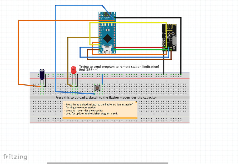
The above is the hardware setup as I was using it, note the 10uF capacitor.
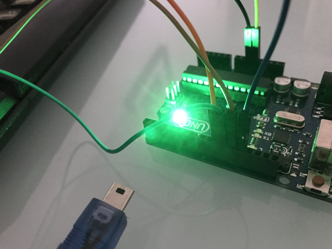
The led here is just for debugging. I used it to make sure I am getting the bytes and was really thing to forward them to the remote station (write the to the rf24 registers over SPI). If you need the debug code you can get it here Using AVRDude to flash the bootloader
Once you have the above local station connected you will need to flash the remote station with the custom bootloader who has the OTA support (note that the remote station hardware configuration configuration is actually the same as the above except the capacitor)
First this is to compile the bootloader once you have that you can run avrdude commands against it in order to flash the remote station. by the end of this process you should have an bootloader.hex file.
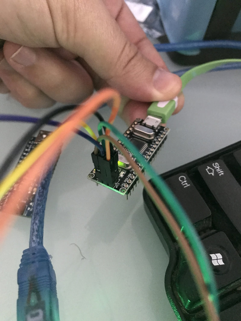
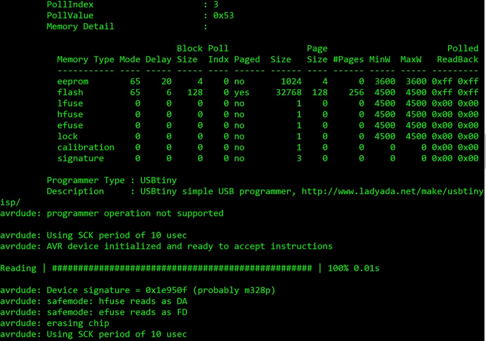
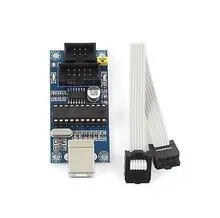
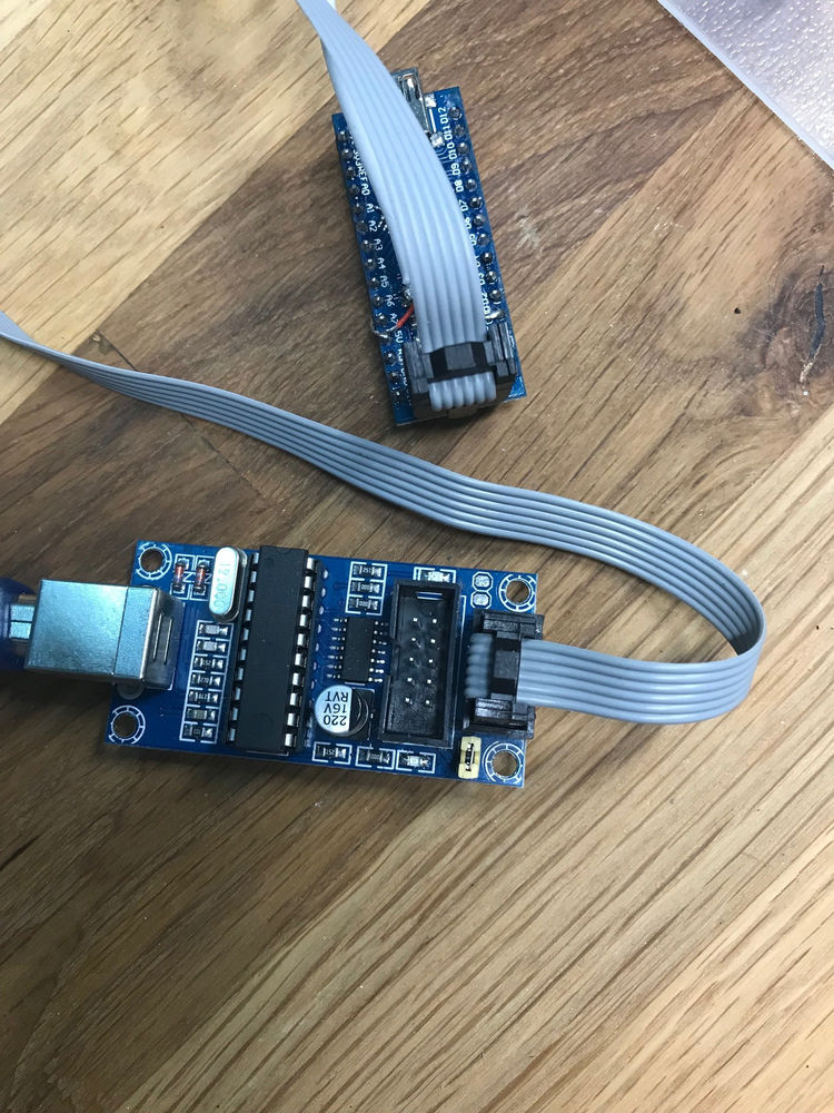
To flash the ota-bootloader hex file you will need 2 commands and an AVR Programmer, You can probably use another Arduino to burn the bootloader but using the programmer is much more convenient Just connect the AVR Programmer to the computer and to the Arduino header like this Flashing commands for avrdud
Code Editor
Note the 0xDA on the first command - it will not work without it.
optiboot_atmega328_without_watchdog.hex is the compiled bootloader hex file. Btw, I compiled my bootloader without the watchdog option (by default it will reset into bootloader every 10 sec or so to allow remote bootloading automatically, in my code I just added to my sketch the option to reset the Arduino when it gets a specific command) - read more here When this is done you should see something like that: 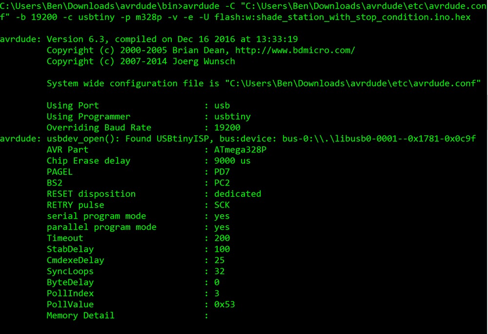
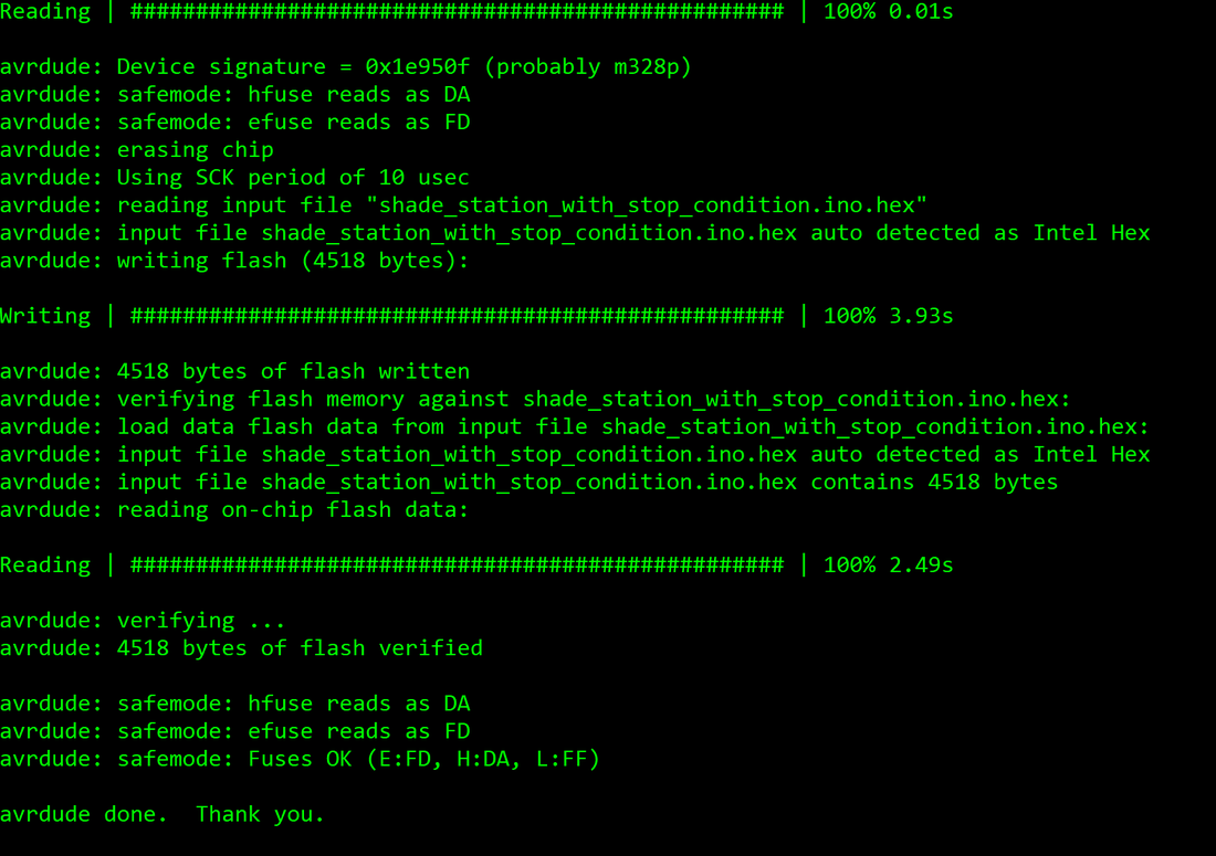
Great! now our remote station is ruining our new bootloader!
All that is left out is to run an avrdude command to flash the local station as if it the remote one - we will just flash our hex file (the same way Arduino IDE does behind the scenes).
When you compile you sketch on Arduino IDE it just puts it on a directory on your computer
I usually just copy it to my avrdude directory and flash it from there. To read more about getting the sketch hex file read here. If you need more here with flashing the boot loader check this. The most important things to remember are:
Finally check these links to get the Hardware and the tools needed to get the job done:
Arduino board: http://s.click.aliexpress.com/e/ZBeuJey
USBtinyISP AVR ISP programmer bootloader: http://s.click.aliexpress.com/e/aUvjA2F All the Arduino schemes attached here where generated with the cool tool: http://fritzing.org/home/ Hope it will serve you all well, Fill free to comment or email me with questions. Please subscribe my Youtube channel. And my facebook page. If your are learning to code to Arduino and you write your own sketchs sooner to later you will need to learn about avrdude, so let's do that. 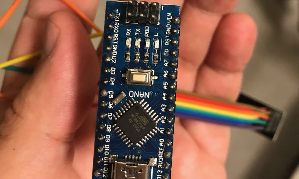 avrdude is a command line utility developed by Atmel. It is used to burn sketches to your Arduino, configure your Arduino register and fuses and also flash a different bootloader then the stock one for example the optiboot a smaller bootloader which will free up some memory space for your sketch. ExampleThis command will burn your Arduino with custom bootloader hex file.
Check out this article about this custom bootloader to learn more. You can learn how to install it here. if you are not familiar with adafruit you should definitely do so. This site by ladyada explains everything you should know about avrdude commands.
While building my SmartHomeDIY project I encountered a problem trying to use multiple SPI devices connected to the same Arduino.
Although the SPI bus should support multiple devices at the same time (toggling the Chip-Select line), this does not always work (mostly due to part using the bus not respecting the chip select or other configuration issues). So after reading for some time and experimenting I came up with the following solution. learn more about transistors here 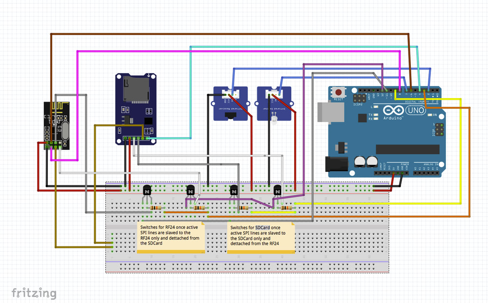
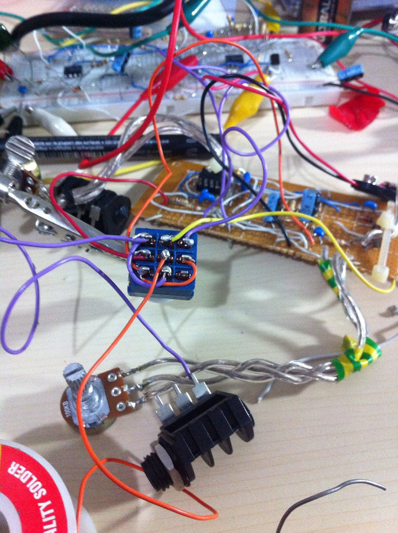
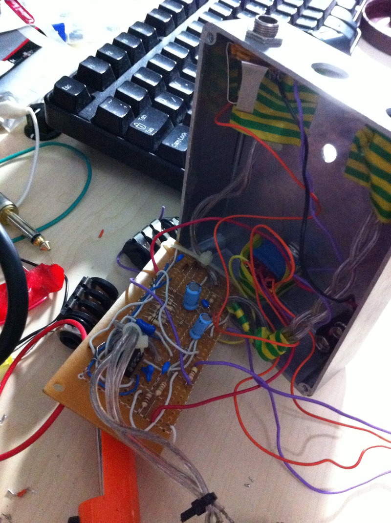
IR Station using multiple SPI devices.
The above station is an IR recorder and transmitter station.
It can be set into recording state which then saved the recorded IR-in data into and SDCard connected over SPI. But when not in recording mode it will listen over the RF24 (also connected via SPI) for commands. Once a command is given it will try to send the IR code request (for example turn TV on) To do that it will again have to move to SDCard mode and read the previously recorded data and retransmit it over the IR out LED. So to solve this I have connected the SPI lines to couple of transistors/switches, They just CUT the lines of the component which is not being used at the moment and there for prevent the SPI lines collision. Attached is the code and hardware layout to do just that Note that it does not matter which type of project you have. You can always do the same transistor-switch trick to cut of the problematic SPI lines while using the others. A special note for the transistor configurations, It will not work if you design you transistor configuration as usually suggested, which means to set a logic level by design at the output of the transistor so that the base will toggle the out voltage (same as an amplifier). Instead I set the signal to go trough the transistor, which needed so testing to select the transistor which does not affect the actual signal (it will depend on the transistor type, spec and configuration...) So it took me some time to figure out the right transistor values and configuration. For trail and error I used this logic analyzer 8 logic lines or better yet one of these pro logic analyzers or one from ebay and there is also a very cool one which has 8 digital channels and one analog - perfect for beginners. I inspected the incoming signal and the outgoing signal to make sure the transistor does not temper with the incoming signal so everything will continue to work as expected (the transistor are transparent to the actual data) You could also try this Hantek 6022BE PC USB Digital Oscilloscope which is working perfectly on Window 10 environment. You could also get one on ebay You could also use this logic multiplexer [8 Channel Logic Level Converter Convert TTL Bi-directional] to do the same job which I have not tested yet. But I think my way is more fun! :) |


 RSS Feed
|
|
|